

 PDF
PDF ePub
ePub Citation
 Print
Print


INTRODUCTION
The orthodontic microimplant (MI), typical of the skeletal anchorage system, is being increasingly used in contemporary orthodontics. MI has allowed clinicians to overcome problems such as anchorage instability or patient compliance dependency, which occur with traditional anchorage methods.1-3 Various MI systems, while widening the domain of treatment possibilities, have so far exhibited a fairly high success rate.4 However, these small non-osseointegration-based implants do face problems such as occasional loosening and failure.
MI failure tends to occur during the first few weeks following placement.5,6 Therefore, improving early-phase stability is an important step toward enhancing the reliability of MI therapy. One possible approach is surface modification.
Surface modification of MIs is not a new idea, but various methods have already been tested and reported as effective both in animal7,8 and human studies.9,10 Most previous studies, however, have focused primarily on improving the quality and speed of osseointegration of dental implants. With the belief that ultimately it is the surface topography that directly affects the retention and biocompatibility of an implant, various methods have been tried, including sandblasting, laser treatment, acid etching, coating with hydroxyapatite, and anodization.11-17 Among these techniques, the surface anodization method, which is relatively simple, appears to be potentially useful for MI systems.
Effects of anodization on the long-term performance of dental implants have shown promise. Anodized titanium implants induced a strong reinforcement of bone response, resulting in a higher clinical success rate.18,19 However, whether these implants can be used as MIs remains to be seen given the differences in size, loading condition, and duration of function as compared to dental implants. MI systems are frequently inserted using the self-drilling method, but in earlier experiments, drilling and self-tapping were used as the modes of implant insertion,13-15 and the anodized surface should be proven strong enough to resist the insertion torque. Most importantly, anodization should be proven to improve the stability of MI during the first few weeks, i.e., the critical period for MI success.
Accordingly, this study was designed to investigate the effect of anodization on the early-phase retention capacity of MI. The removal torque and the interfacial shear strength of anodized and machined MIs (which were identical except for surface characterization) were compared at 6 weeks after implantation in the rabbit tibia.
MATERIALS AND METHODS
Animals and implants
Three mature white rabbits, each 10 months old and weighing 3 - 4 kg, were used as experimental animals. The animals were cared for in compliance with an approved protocol from the Institutional Animal Care Committee of Kyungpook National University Hospital (Daegu, Korea).
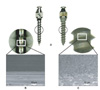
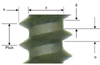
A total of 36 Absoanchor® MIs (Model SH1312-6; Dentos Inc. Daegu, Korea), made of titanium alloy (ELI, ASTM Grade 23), 6-mm long with a diameter of 1.3 mm at the neck and 1.2 mm at the apex, were used. Half had a machined surface (n = 18; machined group), and the remaining had an anodized surface (n = 18; anodized group). Anodization was carried out using the process described by Suh et al.20 to form a surface layer that included titanium dioxide enriched with Ca and P ions. Figure 1 presents the surface textures observed with a scanning electron microscope (S-4200; Hitachi, Tokyo, Japan). Instead of machining lines, characteristic microporous structures were displayed on the anodized surface. Suh et al.20 reported that the surface roughness (Ra) of an anodized surface was 0.73 ± 0.02 µm as compared to 0.24 ± 0.12 µm for an as-machined one.
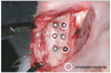
Each animal received 12 MIs: 6 were placed in the diaphysis of each tibia. In each tibia, 3 anodized and 3 machined implants were placed. To ensure an even distribution of bone sites for each group of implants, the implant placement sequence was such that every anodized implant was followed by a machined implant in every row and column as shown in Figure 2. Both groups of implants were driven in using the self-drilling method without indentation.
Torque measurements
When the implants were screwed in, we ensured that they were screwed short of full tightness. The final tightening turn for each implant was made using a custom-made driver connected to a digital torque gauge (E-mobile tech D 17000 series; SEEC, Seoul, Korea) that measured the peak insertion torque needed to achieve full tightness. The peak insertion torque at which the implants were fully tightened was measured in Ncm units with an accuracy of 0.001. The surgical site was then closed. Vaseline gauze dressing was used to cover the sutured area so that the surgical site could be opened later with minimum distraction of the implanted site. The surgeries were performed by an experienced orthodontist.
After a healing period of 6 weeks, during which the woven bone was replaced by lamellar bone,21 the animals were killed, and the soft tissue on top of the implants was carefully removed. The maximum torque needed to unscrew the implants, i.e., the peak removal torque, in 3 animals was measured using the digital torque gauge described above.
Statistical analysis
Statistical analysis was performed using SPSS for Windows 14.0 (SPSS Inc., Chicago, IL, USA). First, the Shapiro-Wilk normality test was performed to verify normal distribution of the torque data. Analysis of covariance (ANCOVA) was then employed to compare the group differences in terms of torque measurements. For ANCOVA of the removal torque, the insertion torque was used as a covariate to eliminate possible effects of the initial mechanical pressure imposed on the interfacial bone at the stage of insertion, which might have been influenced by bone characteristics or other surgery factors in addition to surface anodization. Statistical significance was determined at p < 0.01.
Calculation of shear strength at the implant/bone interface
For a meaningful comparison of the surface characteristics with the results from other studies based on MIs of different designs, the interfacial shear resistance between the implant and bone was assessed.
Torque is a product of the interfacial shear resistance and the distance from the interface to implant axis. Thus, the amount of torque created by a pitch length of implant, Tpitch, is:
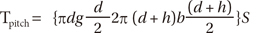
where the variables used in Equation (1) are as shown in Figure 3. S represents the interfacial shear resistance during insertion or the interfacial shear strength during removal.
The amount of torque created by 1 mm length of the implant is obtained by dividing Tpitch by the pitch length (= 0.5 mm for SH1312-6 MI). Then, the torque created by cortical bone, Tcortical, is:
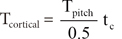
where tc is the cortical bone thickness, which was measured at approximately 1.5 mm.
In this study, the insertion and removal torques were assumed to be created by cortical bone only, since all the MIs were placed in the tibial diaphysis consisted mainly of cortical bone. Finally, S during insertion and/or removal can be calculated using Equations (1) and (2).
RESULTS
All the implants were placed without fracture during the insertion and remained stable during the 6 weeks that followed. No implant exhibited excessive mobility prior to and during the removal. Direct visual observation did not reveal any degradation of the anodized surfaces after removal.
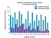
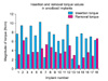
Figures 4 and 5 show the magnitude of the peak insertion and removal torque values for individual implants. As compared to the insertion torque, the removal torque, in general, was reduced at 6 weeks after implant placement, except in the case of 3 implants. These 3 implants, which showed an increase in torque at removal, were in the anodized group.
The Shapiro-Wilk normality test revealed that all the torque data were compatible with a normal distribution. The p values for insertion torque data were 0.175 and 0.248 for the machined and anodized implants, respectively. With regard to removal torque data, the p-values were 0.753 and 0.228 for the machined and anodized implants, respectively.
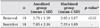
Table 1 presents the results of ANCOVA. No significant difference in the insertion torque of the machined and anodized implants was indicated. In contrast, a significant difference was noted in the magnitude of the removal torque recorded for anodized (3.79 ± 1.39) and machined (2.05 ± 1.07) group implants (p < 0.01); these values were obtained under adjustment of the peak insertion torque.
The mean interfacial shear strength between the implant and cortical bone at insertion was calculated to be 19.72 and 20.22 MPa for the anodized and machined implants, respectively, and at removal, the values changes to 10.6 and 5.74 MPa, respectively.
DISCUSSION
The drop in the removal torque for most of the implants as compared to their respective insertion torque (Figures 4 and 5) can be related to peri-implant bone remodeling. When an implant is placed, it is retained by mechanical purchase from the normal bone. The insertion torque, therefore, is a result of the press fit between the implant and well-calcified bone. During the healing period, as the peri-implant bones undergo remodeling, the pressure at the implant/bone interface falls, and implant retention is increasingly gained from the newly formed bone. The removal torque value becomes dependent more on the extent of bone formation and healing and the extent of mineralization of the newly formed bone. The fall in torque can also be attributed to the occasional presence of soft tissue between the bone and implant. A localized inflammatory response might be a contributing factor.22-24
The effects of MI surface topology with regard to bone remodeling needs attention. As shown in Figure 1, the surface of the anodized layer had more porosities and unevenness in comparison with the machined surface. These microfine irregularities, similar to those reported in previous studies,20,25,26 might have created an uneven stress field in the peri-implant bone: higher stresses near elevations and lower stresses near depressions on the MI surface. This uneven stress could have triggered differential remodeling of the interfacial bone, which could have led to a three-dimensional bone structure at the implant/bone interface, which can in turn play an important role in enhancing mechanical locking during removal.
Effect of surface roughness was more evident in the initial phase following the implant placement. An experiment spanning 1 year27 revealed that bone formation around implants placed in rabbit bone did not show much difference in terms of surface roughness, except in the initial phase. Lack of an active response in the later phase may be because after a turn-over of the interfacial bone, the stress field on the interfacial bone became rather homogeneous and so did the bone remodeling there until eventually it reduced to a level that maintained homeostasis. On the other hand, it may indicate that anodization-driven surface irregularities are effective for enhancing the early-phase retention ability of MIs.
The overall level of insertion torque, or the insertion stresses at the interfacial bone, is an important ingredient in MI stability as an increase in stresses (or strains) beyond a certain threshold can result in microdamage and accelerate bone resorption,28 deteriorating implant stability. In order to keep the interfacial stresses within the physiological range, the insertion torque can be used as a safe guide. Motoyoshi et al.29 recommended using an insertion torque in the range of 5 to 10 Ncm for a 1.6-mm-wide and 8-mm-long MI. Based on a first-order approximation assuming a proportionality between the torque and length, and between the torque and square of implant diameter,30 the appropriate torque for a 1.3-mm-wide and 6-mm-long implant would be in the range of 2.5 to 5 Ncm. In this study, the mean peak insertion torque of most implants were twofold higher than this value (Table 1), which might have led to initial bone damage during insertion. On the other hand, the insertion torque of approximately 2 Ncm exhibited by 2 implants (#7 and #13) in the anodized group appeared to be acceptable. Thus, the rise in the magnitude of the removal torque observed on 3 occasions, including these 2, may reflect the absence of a retarding factor such as excessive stresses that might have aided in bone-implant association. In an attempt to rule out the possibility of error induced in the conclusion due to possible inaccuracies in reading results for these 3 anodized implants, we conducted a statistical analysis that excluded these data. Doing so, however, did not skew our results.
Some researchers31,32 believe that Ca and P enrichment of the anodized surface layer helps achieve a chemical bond between the implant and bone, resulting in stronger interfacial shear strength between the anodized implant and bone. From our results, it is difficult to decide whether a chemical bond was formed. Determination of the exact contact surface area between the implant and bone using histomorphometry and determination of the extent of calcification of the bone could be used as confirmatory tests, but these were not used in this study.
As seen in equation (1), torque is composed of 2 factors: the implant design factors or the terms enclosed in parenthesis { } and the interfacial shear strength S. For a quantitative assessment of the effects of the surface characteristics of implants, one needs to isolate S from the torque equation. Although not many studies have dealt with this subject, a recent study by Morais et al.33 measured S between the rabbit cortical bone and a machined MI of Ti-6Al-4V material, 2 mm in diameter. After a healing period of 12 weeks, interfacial strength as high as 12.34 MPa was reported, and this was much higher than the values recorded for machined implants and even higher than that recorded for anodized implants in this study. A thorough examination, however, revealed that the formula used by Morais et al.33 was imperfect. Recalculation using equations (1) and (2) yielded a value of 5.46 MPa instead of 12.34 MPa, which is close to the results we obtained for the machined implant and suggested that the present findings were reliable.
This animal experiment revealed that anodized implants have a retentive advantage at 6 weeks after placement. However, the anodization procedure increases the manufacturing costs of implants and consequently the total cost incurred by patients. Moreover, clinical studies that test these results in humans need to be conducted.
CONCLUSION
On the basis of our 6-week observation, we concluded that anodizing titanium alloy orthodontic MIs significantly increased their interfacial shear strength and/or removal torque as compared with machined ones. This increase might enable anodized MIs to withstand orthodontic loading more successfully by providing better mechanical resistance during the important early phase after MI placement.
 XML Download