Abstract
The human heart is a complex organ in which many complicated congenital defects may happen and some of them require surgical intervention. Due to the vast complexity of varied anatomical presentations, establishing an accurate and consistent nomenclature system is utmost important to facilitate effective communication among pediatric cardiologists, cardiothoracic surgeons and radiologists. The Van Praagh segmental approach to the complex congenital heart disease (CHD) was developed in the 1960s and has been used widely as the language for describing complex anatomy of CHD over the decades. It utilizes a systematic and sequential method to describe the cardiac segments and connections which in turn allows accurate, comprehensive and unambiguous description of CHD. It can also be applied to multiple imaging modalities such as echocardiogram, cardiac CT and MRI. The Van Praagh notation demonstrates a group of three letters, with each letter representative for a key embryologic region of cardiac anatomy: the atria, ventricles and great vessels. By using a 3-steps approach, we can evaluate complex CHD precisely and have no difficulties in communicating with other medial colleague. This pictorial essay revisits the logical steps of segmental approach, followed by a pictorial illustration of its application.
The heart consists of three major segments, namely, the atria together with the systemic and pulmonary veins, the ventricles with their atrioventricular valves and the great arteries with their outflow tracts (1). Anatomy of the malformed heart can be evaluated, classified and presented by segmental approach, which utilizes a simple notation system that enables rapid communication (2). The notation system consists of a group of three letters/parts, which gives respective information on the three major cardiac segments in terms of the visceroatrial situs, the orientation of the ventricular loop, and the relation of the great vessels (23). Supplementary information on the atrioventricular and ventriculoarterial connections and associated anomalies should be added to the three-part notation system for clear, precise description. The following paragraphs summarize the steps of Van Praagh's segmental approach.
Firstly, visceral situs is determined by the broncho-pulmonary anatomy and location of the liver, stomach and spleen (3). Morphological right lung has three lobes and its main bronchus in an eparterial position, i.e. directly behind the pulmonary artery (Fig. 1a). The morphological left lung has two lobes with its main bronchus in a hyparterial position, i.e. inferior to the pulmonary artery (23) (Fig. 1b).
Next, atrial situs is determined. Anatomical features such as crista terminalis and broad appendage of the morphological right atrium can help distinguish it from the left atrium which has narrow tubular appendage. But these features may not always be easy to identify on imaging. The rule of venoatrial concordance would be helpful to determine the atrial situs (23), the morphological right atrium usually receives systemic venous return.
Situs solitus (S, _, _) is defined as morphological right lung, morphological right atrium and largest lobe of liver on patient's right side; morphological left lung, morphological left atrium, spleen and stomach on patient's left side. Situs inversus (I, _, _) is designated when all the anatomical structures are inversed. If the patient's anatomy does not fit either solitus or inversus, situs ambiguous (A, _, _) is designated (2).
The following table shows some helpful features to distinguish morphological right and left ventricles (2).
(_,D,_) is designated when the morpholoigcal right ventricle is located on the right side of morphological left ventricle, i.e. D-loop. (_,L,_) is designated if their sides are reversed.
The great vessels relation is analyzed at the level of the aortic and pulmonary valves, if these structures are difficult to identify on imaging, the aortic root and main pulmonary trunk are identified for analysis.
The normal solitus position (_,_, S) is defined as aorta right posterior to the main pulmonary artery (23) (Fig. 1c) The mirror image of this relation with aorta left posterior to the main pulmonary artery is designated as inversus (_,_,I) (23). Transposition is usually seen with the aorta anterior to the main pulmonary artery, with right anterior being dextrotransposition (_,_,D-TGV) (Fig. 2a); and levotransposition (_,_,L-TGV) when aorta is left anterior to main pulmonary artery (23) (Fig. 2b) A side-by-side relation of aorta and main pulmonary artery in the coronal plane is usually described as malposition, with D-malposition (_,_,D-MGV) and L-malposition (_,_,L-MGV) if the aorta is rightward of and leftward of main pulmonary artery respectively (2).
Finally, to complete the picture, further details on atrioventricular connection, ventriculoarterial connection, and associated abnormalities would give accurate anatomical diagnosis (3). Atrioventricular connection may be concordant, discordant or ambiguous when there are two ventricles (3). In case of univentricular heart, the atrioventricular connection may be double inlet and absent right/left connection (3). Ventriculoarterial connection may be described as concordant, discordant or double outlet right / left ventricle (3).
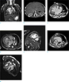
A newborn baby girl developed chest retraction after birth. Findings of atrioventricular septal defects were detected on echocardiogram. The patient's visceral, cardiac and vascular anatomy was well demonstrated by cardiac MRI and CT.
Patient's visceroatrial situs is shown to be situs ambiguous with left isomerism.
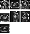
An eight years old girl with antenatal diagnosis of congenitally corrected transposition of great vessels. She remains well with satisfactory exercise tolerance. She is planned for observational management. The patient's anatomy is well demonstrated by MRI.
A three years old boy with antenatal diagnosis of atrioventricular septal defect. He was born at 37 weeks by normal delivery. He had severe atrioventricular valve regurgitation and was treated by pulmonary arterial banding and valvular repair at one month old, bidirectional cavopulmonary shunt was performed at six-month old. The patient's anatomy is demonstrated by pre-operative CT.
Patient's visceroatrial situs is shown to be situs ambiguous with right isomerism.
Cardiovascular anatomy is analyzed in a stepwise fashion based on segmental situs and alignments (4). Segmental approach can give a concise anatomical diagnosis for congenital heart disease. Its simplicity allows effective communication among specialists. Complicated cases can also be accurately characterized.
Figures and Tables
 | Fig. 1(a) Patient with isolated ventricular septal defect, CT demonstrates example of normal eparterial right main bronchus (arrow) located behind the pulmonary artery (RPA). (b) Patient with isolated ventricular septal defect, CT demonstrates example of normal hyparterial left main bronchus (arrow) located inferior to the pulmonary artery (LPA). (c) Patient with isolated ventricular septal defect, CT demonstrates example of normal situs of great vessels with aorta (A) right posterior to the main pulmonary artery (P). |
 | Fig. 2(a) Patient with dextro-transposition, CT showing aorta (A) located right anterior to the pulmonary artery (P). (b) Patient with levotransposition, CT showing aorta (A) located left anterior to the pulmonary artery (P). |
 | Fig. 3(a) Patient with atrioventricular septal defects, coronal localizer showing visceral anatomy: bilateral hyparterial bronchi (arrows) passing inferior to bilateral pulmonary arteries (PA) and left-sided stomach. (b) Patient with atrioventricular septal defects and situs ambiguous, CT showing visceral anatomy: midline liver and multiple spleens (arrows). (c) Patient with atrioventricular septal defects, axial CT showing atrial anatomy: large atrial septal defect with common atrium. Pulmonary veins are seen draining to common atrium at midline. Cardiomegaly and dextrocardia associated with collapsed right lung are noted. (d) Patient with atrioventricular septal defects, a diastolic frame from 4-chamber cine showing that the morphological right ventricle is located on the right side of morphological left ventricle. The right ventricle contains coarse trabeculation and moderator band (arrow) along its septal wall. The left ventricle has smooth septal surface. (e) Patient with atrioventricular septal defects, a frame from short axis cine showing the coarse trabeculations in the right ventricle and the fine trabeculations of the left ventricle. A muscular ventricular septal defect is also seen (arrow). (f) Patient with atrioventricular septal defects, CT showing the normally positioned aorta (A)right posterior to the pulmonary artery which is dilated due to pulmonary hypertension. The pulmonary artery arises from the right ventricle and normal subpulmonic muscular conus (arrows) is seen. (g) Patient with atrioventricular septal defects, a frame from left ventricular outflow tract cine showing aorta arising from left ventricle. Associated normal aortomitral continuity (arrow) is noted. |
 | Fig. 4(a) Patient with congenitally corrected transposition of great vessels, coronal localizer image showing situs inversus with left-sided liver and inferior vena cava, and right-sided stomach. The right pulmonary artery (RPA) is seen crossing superior to the right main bronchus (hyparterial, arrow). Thoracic aorta (A) descends on the right side. Inferior vena cava (IVC) drains into the left-sided morphological right atrium (RA). (b) Patient with congenitally corrected transposition of great vessels, axial localizer showing pulmonary (arrow) draining into the right-sided morphological left atrium (LA). (c) Patient with congenitally corrected transposition of great vessels, coronal localizer showing superior vena cava (SVC) draining into the left-sided morphological right atrium (RA). (d) Patient with congenitally corrected transposition of great vessels, morphological right ventricle with moderator band (arrow) and coarse trabeculae is seen rightward of morphological left ventricle (D-loop). (e) Patient with congenitally corrected transposition of great vessels, aorta arising from morphological right ventricle, which contains coarse trabeculation. Subaortic muscular conus (arrow) is seen separating the arotic valve from the tricuspid valve. (f) Patient with congenitally corrected transposition of great vessels, pulmonary artery is seen arising from the morphological left ventricle, with no muscular conus. Mitropulmonic continuity is seen (arrow). (g)Patient with congenitally corrected transposition of great vessels, the aorta (A) is located right anterior of the pulmonary artery (PA), indicating D-transposition. |
 | Fig. 5(a) Baby with atrioventricular septal defects, CT with coronal reformat and lung window setting showing the branching of left and right main bronchi into upper lobe bronchus and bronchus intermedias, indicating bilateral morphological right bronchial tree and trilobed lungs. (b) Baby with atrioventricular septal defects, dextrocardia with large atrial septal defect, the atria are grossly dilated due to regurgitation. Left atrium (LA) is seen receiving the pulmonary veins (PV). Crista terminalis (arrow) is seen within the right atrium. (c) Baby with atrioventricular septal defects, morphological right ventricle (RV) is located right to the left ventricle (LV). Coarse trabeculations and moderator band along the septal wall are seen within the morphological right ventricle. Thin streak of contrast across the apical septum represents a small ventricular septal defect (arrow). (d) Baby with atrioventricular septal defects, aorta (A) with subaortic muscular conus (arrows) is seen arising from morphological right ventricle (RV). There is no fibrous continuity between tricuspid and aortic valves. (e) Baby with atrioventricular septal defects, pulmonary artery arises from left ventricle which lacks muscular conus along its outflow tract. There is fibrous continuity (arrow) between pulmonary and mitral valves. (f) Baby with atrioventricular septal defects, aorta (A) is right anterior to the pulmonary artery (PA), indicating D-transposition. |
Table 1
Differentiation between Morphological Right and Left Ventricles

Acknowledgements
There is no conflict of interest. All authors contribute equally in this review article.
References
1. Brandt PW, Calder AL. Cardiac connections: the segmental approach to radiologic diagnosis in congenital heart disease. Curr Probl Diagn Radiol. 1977; 7:1–35.
2. Schallert EK, Danton GH, Kardon R, Young DA. Describing congenital heart disease by using three-part segmental notation. Radiographics. 2013; 33:E33–E46.
3. Lapierre C, Dery J, Guerin R, Viremouneix L, Dubois J, Garel L. Segmental approach to imaging of congenital heart disease. Radiographics. 2010; 30:397–411.
4. Van Praagh R. The segmental approach clarified. Cardiovasc Intervent Radiol. 1984; 7:320–325.


 PDF
PDF ePub
ePub Citation
 Print
Print


 XML Download