

 PDF
PDF ePub
ePub Citation
 Print
Print


I. Introduction
Restoration of the endodontically treated tooth is a critical final step for successful endodontic therapy. Many dentists assume that endodontically treated teeth are weakened and more prone to be fractured due to dessication or premature loss of fluids supplied by vital pulps1).
An in vitro study by Panitvisai and Messer2) demonstrated that access preparations result in greater cuspal flexure, increasing the probability of cuspal fracture, because the preparation results in a deep and extended cavity, reducing the amount of dentin to a critical extent3). In general, it was known that the optimal restoration of an endodontically treated posterior tooth should be a cast inlay with cuspal overlays or, if necessary, a full crown. An extracoronal restoration that covers the cusps is the most commonly recommended method for reducing the risk of fracture1,4,5). Other forms of coronal coverage-including gold, ceramic, or resin composite onlays and cusp-covering silver amalgam restorations may also provide endodontic treated teeth with protection against fracture. According to retrospective study6), convincing evidence was reported that 1273 endodontically treated teeth were investigated to identify significant causes of failure and concluded that the presence of cuspal coverage was the only significant restorative variable to predict long-term success.
Hannig et al.1) suggested that endodontic treatment does not cause teeth to become more brittle, and dehydration after endodontic treatment does not weaken the dentinal structure either. A recent study reported that endodontically treated teeth and their contralateral vital pairs exhibited similar biomechanical properties, such as punch shear strength, toughness, and load required for fracture7).
Reeh et al.3) suggested that endodontic procedures have only a small effect on the tooth, reducing the relative stiffness by 5%. This numerical value was less than that of an occlusal cavity preparation (20%). The largest losses in stiffness were related to the loss of marginal ridge integrity. Mesiooccluso-distal (MOD) cavity preparation resulted in 63% average loss in relative cuspal stiffness, and MOD and endodontic access cavities resulted in 80% loss in cuspal stiffness8). This means that every effort should be made to maintain at least one marginal ridge in the endodontically treated teeth.
When endodontic access can be conservative and proximal tooth structure remains intact, simple restoration of the endodontic access opening may be adequate. It seems as if the bonding ability of restorative systems to cavity walls is more effective on the fracture resistance than other mechanical features.
In the decreased tooth deflection after restoration with posterior composites and dentinal bonding agents in conservative preparations, tooth movement was similar to that of cusps in the unaltered tooth5).
The ability to predictably restore an endodontically treated tooth to its original strength and the fracture resistance without placement of a full-coverage restoration could provide patients with potential periodontal and economic benefits. More recently emphasis has been placed on intracoronal strengthening of teeth to protect them against fracture9). Dentine bonded reinforced composites resins and amalgams, adhesive ceramic inlays that provide internal reinforcement of teeth without occlusal coverage have been advocated1).
Trope et al.4) showed that the resistance to fracture of endodontically treated premolars was significantly increased when the teeth were restored with composite resin placed intracoronally after acid etching. Recently these findings were confirmed by Reeh et al.5) who found that endodontically treated teeth restored with composite resin after enamel and dentin etching were significantly stronger than those left unrestored and their strength was almost strong same as intact teeth.
Composite resin bonded to enamel and dentine has been found to restore at least part of the stability of the unprepared tooth while exacting less additional preparation8). In terms of fracture resistance, no significant difference was observed between direct composite resin restorations and ceramic inlays10). The frequency of cusp fracture of endodontically treated premolars was investigated in a retrospective study. After endodontic therapy, the teeth were restored either with a MOD amalgam filling or with enamel bonded MOD resin filling. A very high frequency of cusp fracture was found in premolars restored with amalgam11).
Studies have shown that after endodontic treatment, teeth restored with bonded restorations are more resistant to fracture compared with those restored with silver amalgam, but both bonded silver amalgam and bonded cast metal inlays have been advocated for reinforcement of prepared teeth1).
Finite element analysis (FEA) is particularly useful in dentistry since it can readily cope with both the complex geometry of a tooth and its supporting structures along with the large variation in physical properties. FEA studies concerned about MOD restorations of endodontically treated maxillary premolars are numerous. But FEA study of conservative bonded access cavity restoration is rare.
The objective of this study was to investigate the effects of four conservative restoration types such as composite resin, amalgam restorations, ceramic and gold inlay restorations on the stress distribution of endodontically treated maxillary second premolar under various occlusal loading conditions, using 3 dimensional (3D) FEA.
II. Materials and Methods
1. Finite element model
To develop a 3D FE model, intact normal extracted human maxillary second premolars were selected in this study. The premolar were scanned serially with Micro-CT (SkyScan 1072; SkyScan, Aartselaar, Belgium) to exposure the tooth sections perpendicular to the long axis of the tooth (58 µm in thickness) and parallel to the occlusal plane. 3D-DOCTOR (Able Software Co., Lexington, MA, USA) image processing software was employed to detect the boundaries of enamel, dentin and pulp from the sectioned two dimensional images and to make a three-dimensional surface model. Rhino 3D (Robert McNeel & Assoc., Seattle, WA, USA) was used to reduce useless nodes from the surface model and ANSYS (Swanson Analysis Systems, Inc., Houston, USA) was used to mesh.
All the vital tissues were presumed linearly elastic, homogeneous and isotropic. The corresponding elastic properties such as Young's modulus and Poisson's ratio were determined according to literature survey12,13) (Table 1).
The periodontal ligament was assumed to be 0.3 mm wide, and the dimensions of surrounding compact and cancellous bone were derived from standard texts14,15). The alveolar bone was also generated by growing the outer surface of the tooth model from 2 mm below the CEJ. The pulp region was modeled as being hollow. In these models, the outer surface of the alveolar bone model was fixed in order to prevent rigid body motion for FEA.
The model was fixed to restrict the mesiodistal movement. In all loading cases, the base nodes of simulated alveolar bone were assumed fixed to prevent rigid body motion.
2. Restoration
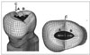
Access cavity was filled with amalgam, composite resin, ceramic, or gold over glass ionomer base (Figure 1). The GIC bases were filled up to ideal cavity depth from canal orifice.
3. Loading conditions
In order to determine the load conditions such as magnitudes, directions, occlusal contacts (i.e., point or surface, centric or eccentric), preliminary investigation was performed using the data gathered by literature review19). Based upon these data, 170 N was assumed as the chewing force for premolars and 500 N was assumed as the heavy parafunctional load of bruxism and traumatic occlusion.
A Static force was applied for the following loading conditions (Figure 2). The eccentric heavy occlusion was simulated with two loading conditions. Load-1 represented the perpendicular load of 500 N at the restored surface of upper third of palatal incline of buccal cusp. Load-2 represented the perpendicular load at the restored surface of upper third of buccal incline of palatal cusp. And physiologic centric occlusion was simulated with Load-3. Load-3 represented a unit load distributed at the two points corresponding to centric occlusion (perpendicular load of 100 N on the upper third of buccal slope of palatal cusp and perpendicular load of 70 N on the center of mesial marginal ridge).
III. Results
1. Load-1
1) Buccal CEJ
(1)Stress patterns
The difference of stress pattern was not observed along the CEJ of all of the four types of restorations (Figure 3).
(2) Maximum principal stress analysis
Stress of 5.3 MPa was shown at the mesial point area (Node 2) and an even higher tensile stress of 7.4 MPa was shown at the distal point area (Node 8), but compressive stress also manifested in the rest of the areas. There were no differences in magnitude of stresses among the four types of restorations (Figure 4).
2) Palatal CEJ
(1) Stress patterns
Maximum principal stress was distributed along the CEJ and the highest tensile stress was concentrated at the area a little to the distal from the midpalatal. There were no differences in the pattern of stress distributions among the four types of restorations (Figure 5).
(2) Maximum principal stress analysis
Overall, high tensile stress of over 50 MPa resulted along the CEJ with no difference in magnitude of stresses among the four types of restorations. The tensile stress of mesial point area (Node 9) was 55.3 MPa and a peak tensile stress of 144.1 MPa was exhibited at the point little to the distal from the mid-palatal (Node 4) while tensile stress at the distal point area (Node 1) registered 73.4 MPa (Figure 6).
3) Occlusal Central groove
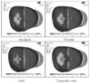
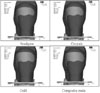
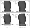
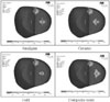
(1) Stress patterns
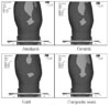
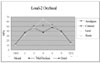
The maximum principal stress was concentrated around the buccal loading point and along the central groove of occlusal surface in a different way among the four types of restorations (Figure 7).
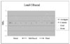
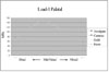
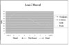
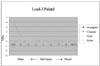
(2) Maximum principal stress analysis
There were differences in stress value among the four types of restorations along the central groove. High tensile stress was concentrated at the mesial (Node 2) and distal (Node 6) marginal ridges. Peak tensile stress of 57.3 MPa was detected at the distal marginal ridge (Node 6) in the case of composite resin restoration and magnitude of stress value was followed by amalgam, ceramic and cast gold restoration (Figure 8).
2. Load-2
1) Buccal CEJ
(1) Stress pattern
Maximum principal stress was distributed along the CEJ and the highest tensile stress was concentrated at the area a little to the mesial from the midbuccal. There were no differences in the pattern of stress distributions among the four types of restorations (Figure 9).
(2) Maximum principal stress analysis
There were no difference in magnitude of stress among the four types of restorations and tensile stress at the mesial point area (Node 1) registered 56.6 MPa. The highest tensile stress of 80.8 MPa was concentrated at mesiobuccal area (Node 2) and stress value was decreased to the distal point area. The lowest tensile stress of 18.1 MPa was concentrated at distal point area (Node 9) (Figure 10).
2) Palatal CEJ
(1) Stress pattern
Maximum principal stress distribution was not detected along the CEJ and there was no difference in the pattern of stress distribution among the four types of restorations (Figure 11).
(2) Maximum principal stress analysis
The weak compressive stress was observed along the palatal CEJ except for distal point area (Figure 12).
3) Occlusal
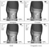
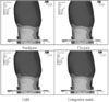
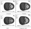
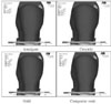
(1)Stress pattern
There were differences in the patterns of stress distribution around the loading point and along the central groove among the four types of restorations. There was no stress distribution on the composite resin restoration (Figure 13).
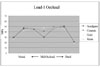
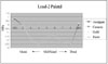
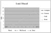
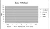
(2) Maximum principal stress analysis
There were differences in stress value among the four types of restorations along the central groove. High tensile stress was concentrated at the mesial (Node 2) and distal (Node 6) marginal ridges. Peak tensile stress of 44.0 MPa was detected at the distal marginal ridge (Node 6) in the case of composite resin restoration and magnitude of stress value was followed by amalgam, ceramic and cast gold restoration (Figure 14).
3. Load-3
1) Buccal CEJ
(1) Stress pattern
Maximum principal stress did not appear except at distal CEJ and there was no difference among the four types of restorations (Figure 15).
(2) Maximum principal stress analysis
Peak tensile stress (19.1 MPa) was concentrated at the distal point area (Node 8) and there was no difference among the four types of restorations (Figure 16).
2) Palatal CEJ
(1) Maximum principal stress pattern
There was no difference in stress pattern among the four types of restorations (Figure 17).
(2) Maximum principal stress analysis
Peak tensile stress (4.0 MPa) was observed at the distal point area, however the overall magnitude of tensile stress was smaller than the buccal CEJ. Compressive stress was observed at both the midpalatal and mesial areas (Figure 18).
3) Occlusal
(1) Stress pattern
Similar stress pattern were present at the loading point C, but there were differences in the pattern around the loading point B among the four types of restorations (Figure 19).
(2) Maximum principal stress analysis
Peak tensile stress (171.9 MPa) was observed around the mesial loading point and there was no difference among the four types of restorations (Figure 20).
IV. Discussion
In sound posterior teeth, buccal and lingual cusps are interconnected by the occlusal enamel and the marginal ridges. As these stabilizing elements are removed during cavity preparation, the cusps are more easily deformed and forced apart during occlusal loading and become more susceptible to cusp or crown fracture8,11,21).
Since dentinal hardness and moisture content in the pulpless teeth are similar to those in the vital teeth1,22), the susceptibility to fracture is believed to be increased due to the cumulative loss of tooth structure during restorative and endodontic procedures 5), not the effect of endodontic treatment itself.
Hardness measurements of endodontic treated tooth that were treated up to 10 years previously indicated no difference in hardness between endodontically treated and vital teeth3). Similiarly, punch shear testing on endodontically treated teeth showed only a small (although statistically significant) reduction in strength of 14%. This suggests that the total effect of endodontic procedures is not great and is in fact comparable to an occlusal cavity preparation 3,22). Lewinstein and Grajower22) in their study of 16 vital and 32 root-filled teeth which had been extracted, indicated that root canal therapy did not affect vickers hardness of dentine, even after periods of 5-10 years.
Endodontic access cavity, and to a greater extent a MOD cavity, can increase this tendency to deflection under mechanical forces. Repeated stresses can greatly reduce the resistance to fracture, causing the tooth to be broken even if the force is far below the loading force required to break a healthy tooth21). Marginal ridges should be preserved and conservative cavity designs and access to the root canals for endodontic treatment will decrease the frequency of fracture in tooth or restoration5).
Ideal final restoration for an endodontically treated tooth should be restored to a certain level of the original tooth stiffness, so as to decrease the mechanical fatigue of the residual cusps. It should also restore its function and esthetics, protect the remaining tooth structure, and resist marginal microleakage.
The objective of this study was to investigate the possibility of success of bonded intracoronal restoration of four restorative materials by the tensile stress analysis of endodontically treated maxillary second premolar under various occlusal loading conditions using a 3D FEA. In this study, conservative endodontic access cavities were simulated with the standard contours (i.e. oval for upper premolars) with sound marginal ridge.
Stress analysis was focused at the CEJ area of buccal and palatal surface based on the reports of many FEA studies12,23-25). Kuroe et al.26) also confirmed by the photoelastic method that a vertical force loaded on the tooth causes stress concentration at the cervical line. Nothing but the tensile stress was observed in this study, because enamel and dentin are less resistant to tensile stress than compressive stress.
In tensile stress analysis of the CEJ of buccal and palatal surface, high stress distribution over the failure range was observed at the midpalatal CEJ under Load-1 and mesiobuccal CEJ under Load-2 in all of the restorations. The peak tensile stress of 144.1 MPa was concentrated at the Node 4 a little to the distal from the mid-palatal under Load-1. The highest tensile stress of mesiobuccal CEJ under Load-2 was 80.8 MPa. Tensile stress of palatal CEJ under Load-1 was higher than tensile stress of buccal CEJ under Load-2. These results revealed a strong association between loading forces of Load-1 and the possibility of failure of enamel and dentin of the midpalatal cervical area by tensile stress.
In the occlusal surface, the tensile stress at the marginal ridges under Load-1 was slightly higher than under Load-2. All of the stress values at the CEJ and marginal ridge were over the limit of mechanical properties of the tooth. Therefore, the Load-1 is considered as the major factor to jeopardize the restoration durability and palatal cusp fracture than Load-2. In these instances of eccentric heavy occlusion, vertical fracture may occur along central groove because tensile stress was shown in the marginal ridge. Milicich et al.27) suggested that vertical fracturing in the contact point area of the peripheral rim can occur when cusps are placed under tension loads.
Trope et al.4) concluded that when loaded to fracture, teeth restored with amalgam or with a cavity preparation alone tended to fracture from the base of the cavity preparation to the cervical area. In the result of another study28) the fractures of lingual cusps occurred in the 55 teeth out of 60.
The fact that lingual cusp fractures occur more often than buccal cusp fractures may be ascribed to tooth weakening during cavity preparations because of the inclination of the tooth and/or the location of the central fossa, which is usually closer to the lingual wall. Lingual cusp fractures ended more frequently above or at the gingival crest in teeth with vital pulps, and in non-vital teeth, fractures ended more frequently below the crest.
It has also been reported that in vivo fractures of palatal cusps of maxillary premolars occur more frequently than fractures of those of the buccal cusps29). The frequency of cuspal fracture and its relationship to tooth anatomy has been investigated by Khera et al.30) Their results showed that the functional cusps were significantly wider than the nonfunctional ones, although maxillary premolars had smaller functional cusps.
Because of the special risk of the fracture of palatal cusps of maxillary premolars revealed by the results of this study, full cuspal coverage was recommended and partial-veneer ceramic crowns covering the palatal but not the buccal cusp also recommended as an alternative approach. This type of restoration would also offer esthetic advantages compared with partial-veneer crowns with buccal-cusp1).
In comparison to the Load-1 and Load-2, the stress distribution of the Load-3 showed no difference in magnitude of stress between four types of restorations. This result suggests that in physiologic centric occlusion such as Load-3, four types of restoration were restorable without full cuspal coverage. The small size of the cavity preparation and the types of restorations in teeth with small preparations did not appear to produce a concentration of stresses high enough to weaken the teeth significantly.
V. Conclusions
Within the limits of this study, following conclusions can be drawn:
Excessive high tensile stresses were observed along the palatal CEJ in Load 1 case and buccal CEJ in Load 2 case in all of the restorations. There was no difference in magnitude of stress in relation to the type of restorations.
Heavy tensile stress concentrations were observed around the loading point and along the central groove of occlusal surface in all of the restorations. There was slight difference in magnitude of stress between different types of restorations.
High tensile stress concentrations around the loading points were observed and there was no difference in magnitude of stress between different types of restorations in Load 3 case.


 XML Download