

 PDF
PDF ePub
ePub Citation
 Print
Print


I. INTRODUCTION
The property improvement of composites enables it to play an important role in indirect restoration. However, the improvement is not effectual unless the right reinforcing materials are used. There has been many reports1-6) in attempt to reinforce mechanical properties of fiber-reinforced composites (FRC) by using different types of fibers and positioning them differently. Recently, some studies reported1,2) that the positioning and adaptation of fiber influenced the load to initial and final failure and deflecting the specimen, and fiber slightly away from the tensile side improved the flexural properties. Lassila et al3) asserted that the fiber rich layer should be spread vertically in order to optimize the stiffness of FRC fixed partial dentures. The maximum effect of reinforcing should be obtained by applying the material right on the tensile side of the restoration. But clinically, the exposure of fiber can cause plaque to accumulate and this may lead the restoration to fail. Additionally in the case of fixed partial denture, clinical design and lab procedure turned out to be much more difficult than experimental design. For these reasons, there were limitations to positioning the reinforcing materials in FRC and proportion of those in restoration was considerably low. In order to take advantage of reinforcing materials with low quantity, the composition and position of reinforcing materials were optimized to transfer tensile stress from occlusion.
Another important factor affecting the mechanical properties of FRC is the adhesion between the reinforcing materials and surrounding composites. If there is not proper adhesion, the stress from occlusion could not be transferred to the reinforcing materials. Then the reinforcing materials would become a void and they might weaken the flexural strength of FRC.
Silane coupling agents have been widely used in dentistry to improve the bond of inorganic substances (glass, quartz etc) and the properties of composites. The silane has bifunctional groups, with one end (CH3O) reactive towards the silica and the other end reactive towards the resin matrix. Therefore, silane acts as a coupling agent, chemically reacting both with the silica and the resin matrix. As for silane, the most desirable application is on the monolayer, which is the most reactive property. If a multi-layer structure is formed in silane, cross-linking may occur and the chance of monomers making cross-links with the silane is reduced. Composites with silanated fillers represent superior mechanical properties than composites with non-silanated fillers. Recently, Alireza et al.7) reported surface treatment by silane coating, sandblasting, combination of silane coating and sandblasting significantly promoted the bond strength of resin cements to glass fiber posts. Debnath et al4) reported interfacial shear strengths glass/resin were greater for silanated specimens compared with unsilanated specimens.
Fracture of FRC due to external force may cause the resin composites matrix, reinforcing materials, or the interface to cracking. The cracking of FRC that occurred in the internal and external side can be evaluated by means of acoustic emission signals. At the point of clinically used FRC, an important parameter might be the initial failure of restoration. Before permanent deformation, damage and initial failure of restoration may induce or accelerate undesirable effects. Initial failure may consequently be a more sensitive or useful an indicator than ultimate strength for experimental strength evaluation and possible interpretation.
Actually, there are many kinds of reinforcing materials (U-beam, I-beam, bundle, mesh etc.), and combinations of the reinforcing materials that have been used. But there had been none of the study on the composition of reinforcing materials yet. The purpose of this study is to evaluate the effects of surface treatment and composition of reinforcement material on fracture strength of fiber reinforced composite inlay bridges.
II. MATERIALS AND METHODS
The experimental design was not aimed at hexahedral specimens but the clinical replicative specimens. A total of 83 fiber reinforced composite inlay bridges were made by one operator with hand instruments and Tescera ATL laboratory kit. All the laboratory procedures were guided by the manufacturer's instruction.
The materials used in this study was shown in Table 1. The reinforcing materials used in this study were quartz fiber in an epoxy matrix, which is in the shape of a U and a I (BISCO. Inc. IL, USA). The reinforcing materials were fabricated to meet the dimensions of the proximal box. After the fabrication, a U-beam with 3.0 mm in width, 2.0 mm in height, 10.0 mm in length was used.
The two I-beams that were used had different diameters; 1.8 mm and 1.4 mm. The I-beam with 1.8 mm diameter was used alone, whereas the one with 1.4 mm diameter was used with the U-beam. I-beams were fabricated only to the length 10.0 mm, and when it was used without the U-beam, two pieces of I-beams were inserted in the composites inlay bridge specimen.
Two kinds of surface treatments were applied; the silane and the sandblast. Porcelain primer (3-Methacryloxypropyl-trimethoxysilane) (BISCO. Inc. IL, USA) was used as a silane, and aluminum oxide that had a particle size of 25 - 50 µm was used for the sandblast (Renfert, Hilzingen, Germany). In addition, to evaluate the role of adhesion of reinforcing material to the composites, 3 holes were made at the U-beam for mechanical aid. Indirect composites system Tescera ATL and Tescera ATL composites that had shade A2 were used. ONE-STEP was used for the bonding agent. The specimens were divided into 11 groups according to the composition of reinforcing materials and surface treatments (Table 2).
1. Specimen preparation
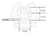
On the dentiform, supposing the missing of Maxillary second pre-molar and indirect composites inlay bridge cavities on adjacent first premolar disto-occlusal cavity, first molar mesioocclusal cavity was prepared with conventional high-speed inlay bur. The depth of occlusal cavities were 2.0 mm and the dimension of proximal box was 4.0 × 2.0 × 1.5 mm (Figure 1).
Impression of dentiform was taken using light body rubber impression material. For composites inlay bridge. build up, the working dies were made with rubber impression and improved gypsum (GC, Leuven, Belgium). For fracture test, the testing dies were made with rubber impression and epoxy resin (Daeheung, Ansan, Korea). The epoxy testing dies were adjusted for fracture strength test.
Surface treatment of reinforcement materials was carried out as follows; Silane was applied twice continuously to the reinforcing material with a brush and left for 1 minute. Sandblast was performed perpendicularly with aluminum oxide (25 - 50 µm) with a distance of 1 cm for 5 seconds. After the sandblast, the reinforcing material was cleaned with ultrasonic unit in distilled water for 20 seconds. For the mechanical retention, 3 holes were made on the U-Beam with a high-speed round bur with a 1 mm diameter.
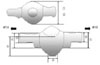
The control group was built up with the Tescera dentin, body, and incisal composites. The layer of the Dentin composites was made as thin as possible on the working die. When the layer was once built up, the specimen was cured in the light cup. Body composites were built up 3 times. Then the Incisal composites were built up to a thickness of about 0.5 - 1 mm. During the build up the body, incisal composites, and the saddle was foamed by a steel ball with a diameter of 4.16 mm to apply to the load. When the final build up of incisal composites was done, the specimen was cured in the heat cup. After curing, specimens were fabricated according to the eight landmarks, for standardization (Figure 2). Fabrication was done by using digital caliper, metal crown depth gauge, high speed polishing burs and soflex disc. Specimens were stored for 1 week in distilled water at room temperature. The composites inlay bridges were set on the testing die using zinc phosphate cement.
In the case of using the reinforcing materials, they were cleaned in acetone for 10 seconds. Silane was applied twice continuously to the reinforcing material with a brush and left for 1 minute. After the silane dried out, ONE-STEP was applied at the reinforcing material with a brush and was left for 20 seconds and blown with air and light cured. The reinforcing materials were placed in the proximal box space of the gypsum working die with using flowable composites (TESCERAFLO) and light cured. Composites inlay bridge was built up with the Tescera dentin, body, and incisal composites as mentioned previously. During the build up of the body and incisal composites, the saddle was foamed by a steel ball with a diameter of 4.16 mm to apply to the load. When the final build up of incisal composites was done, the specimen was cured in the heat cup. After the curing, specimens were fabricated according to the eight landmarks, for standardization (Figure 2). Specimens were stored for 1 week in distilled water at room temperature. The composites inlay bridges were set on the testing die by using zinc phosphate cement.
2. Fracture Strength measurement
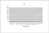
The specimens were placed on the testing zig of Universal testing machine (EZ-tester; Shimadzu, Japan), and put on the steel ball with a 4.16 mm diameter. And then flexural force was applied at a cross-head speed of 1 mm/min until initial crack occurred. The load-deflection curves were recorded with PC and recording software (WinAGS Lite).
III. RESULTS
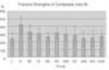
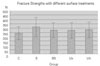
The mean and standard deviation of the fracture strengths of each group were shown in Table 3.
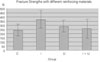
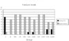
Most of the groups showed higher strengths than the control group, but some groups showed a similar level (Figure 3). Groups using I-beam showed the highest fracture strengths and there were significant differences from the control group and the groups using a combination of the I and U beam (p < 0.05) (Figure 4). Although there was not a significant difference, groups using a combination of the I and U beam showed lower strength than singly using the U-beam. Groups using silane as surface treatment showed the highest fracture strength, but there were other significant differences among each surface treatment (p > 0.05) (Figure 5).
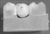
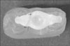
The main fracture pattern of the control group was vertical fracture. However, most of the specimens in groups that used reinforcing material showed delamination (Figure 6). Vertical fracture was occurred at the pontic tooth, but delamination was processed from marginal ridge to the occlusal cavity of abutment tooth obliquely (Figure 7a, 7b). There was definite difference between the fracture mode of the control and reinforcing groups. But, there was no difference of fracture occurrences between both of the first molar and the first premolar (Figure 8a, 8b).
IV. DISCUSSION
Following the minimal invasiveness principle, the composites inlay bridge could be useful when missing space is narrow or has intact adjacent teeth. The failure of composites inlay bridge is supposed to be a failure of tooth-restoration interface. However, in this study, as we want to see a fracture strength of composites inlay bridge itself, the condition of cementation was excluded.
The initial fracture could be acknowledged if following conditions were presented; 1) audible emissions caused by the generation of elastic waves by crack formation, 2) visible signs of fracture, 3) a sharp decline in the load-deflection curve.
Following the classification by Craig and Courtney17), there were three types of fracture mode that could occur while the FRC in a tension type test; those were instantaneous, statistical, and step wise failure. The patterns of initial failure in this study were primarily delamination that was represented running of crack from the occlusal cavity to the marginal ridge and most of those were classified statistical type that had a strain concentration distributed to a wide region may require further load to elongate the crack. Most of specimens in control group were showed vertical fracture and reinforcing groups were showed delamination. Although the fracture strengths of specimen were similar, there were definite different patterns of fracture between control and reinforcing groups.
Ozcan et al5) reported a large amount of resin composites surrounding the fiber at the connector area may decrease the strength. And they also reported in a restoration with small box dimensions, the transmittance of the force was more in the FRC restoration. Volumetric analysis of the groups used different reinforcing materials at the box space; I-beam 63.61%, the I and U beam 47.52%, U-beam 28.27%. However, following the previous results, the group using only the I-beam showed a significantly higher strength whereas even the group using a combination of the I and U beam showed lower strength than using U-beam alone. It seemed that the combination of reinforcing materials didn't work as one unit and there were interferences to transfer the stress between each reinforcing materials. In dental use there were limitations of applying the reinforcing materials. As the limitations of application, the reinforcing materials were placed only in a box space and consequently those were placed at the center of the restoration.
Generally, the higher the degree of monomer conversion, the better the mechanical properties of the composites restoration. The higher degree of conversion could be achieved by increasing either polymerization temperature or light intensity. At the point of shade of composites, the lighter shade it was, the higher rate of conversion it had. A2 shade was chosen for that reason. The higher polymerization temperature increases monomer movement resulting in a higher degree of conversion of C=C bonds of the functional groups of the monomers and lowers the residual monomer content. Tescera ATL was adopted the effect of pressure and high temperature. The chamber pressure was 70psi and when applying heat cup the temperature went to 130℃. All the laboratory procedures were guided by the manufacturer's instruction.
The silane should be made a monolayer on the reinforcing material as if it was formed in multi-layers, the strength of bond between composites and reinforcing materials would be reduced. Many of the previous reported studies4,7) concluded that silane surface treatment was to improve the adhesion between reinforcing materials and resin composites. But, in this study, although treatment of silane presented highest fracture strength, there were not significant differences with other surface treatments. To the reinforcing materials used in this study, manufacture had made the silane treatment on the surface help adhesion. The results can be explained on account of the following reasons. First of all, the additionally applied silane interfered with the adhesion and the sandblast peeled off the surface treatment which the manufacturer had made. Finally, the silane treatment that was applied after the sandblast could not adequately compensate the silane that was peeled off. Additionally, mechanical aid by making the retention holes did not make any differences.
V. CONCLUSION
Within the limitations of the study, the following conclusions were made;
The use of I-beam represented highest fracture strengths (p < 0.05).
In groups only using silane as a surface treatment showed highest fracture strength, but there were no significant differences between other surface treatments (p > 0.05).
The reinforcing materials affect the fracture strength and pattern of composites inlay bridge.
The holes at the U-beam did not increase the fracture strength of composites inlay bridge.


 XML Download