

 PDF
PDF ePub
ePub Citation
 Print
Print


I. Introduction
Success of endodontic treatment depends on many factors, such as correct diagnosis, effective cleaning, shaping and disinfection of the root canals, and a tight obturation. These are all important. However, since the shape of prepared root canal significantly influences on the quality of the root canal obturation, adequate root canal preparation cannot be overestimated. The ideal prepared root canal should have a progressively tapering conical shape which preserves the apical foramen and the original canal curvature without transportation1). Deviation from the canal's natural path during instrumentation is a common procedural error and may present as zipping, canal straightening, and ledging or elbow formation2). In order to avoid this procedural error and achieve the ideal canal preparation, a number of different endodontic instruments and various preparation techniques have been developed.
General understanding of the three-dimensional morphologic characteristics of root canal systems and of the morphologic changes during root canal instrumentation is essential for the successful endodontic therapy3). There have been many different methods to evaluate endodontic instrumentation, including plastic models, histological sections, scanning electron microscopic studies, serial sectioning, radiographic comparisons, and silicon impressions of instrumented canals. However, due to the some inherent limitations of these techniques, better methods with more advantages and improved possibilities have been continually developed4).
The applicability of clinical computed tomography (CT) in endodontics was initially suggested by Tachibana and Matsumoto in 19905). They concluded that, at that time, CT had only a limited usefulness in endodontics due to high costs and inadequate software. Above all, low resolution of CT was an obstacle in the use of CT in endodontic research6,7). Nowadays, however, improvements in technology have led to a miniaturized form, called microcomputed tomography. As a unit of the resolution changed from mm to µm, more detailed visualization of tooth structure was possible.
Currently used Ni-Ti instruments are superior in maintaining the original canal anatomy and reducing the risk of transportation and perforation8). It has been reported that preparation by Ni-Ti instruments requires less force and less preparation time8).
The purpose of this study was to 1) compare the effects of preparation with nickel-titanium GT rotary files and profile .04 in shaping of root canals of extracted human mandibular molars using micro computed tomography (micro CT) and 2) reconstruct the three-dimensional root canal system from the micro computed tomographic data and visualize this.
II. Materials and methods
Specimens and instruments
20 extracted human mandibular molars with fully formed apices were used in this study. Separate mesiobuccal (MB) and mesiolingual (ML) canal were used. According to the Schneider's method, mesial root curvature was 20 degrees or more9). The teeth were stored in 3.5% NaOCl solution throughout the study except during canal instrumentation and micro CT scanning. The rotary instruments used in this study were Profile .04 taper files and GT rotary files (Maillefer, Switzerland). The electric motor used in this study was Endo DTC (Aseptico, USA) and it was possible to control RPM and torque with this device. The RPM and torque were controlled and carried out according to manufacturer's recommendations.
Specimen's preparation
Conventional access openings were prepared and the crown portion above CEJ was cut with low-speed diamond saw (Isomet, Buehler Ltd, USA). Crown portion were cut to help stabilize setting of the tooth on the specimen holder of micro CT and locating stop accurately during preparation. The teeth were randomly distributed into two experimental groups.
In group 1, MB and ML canals were prepared in a crown-down method. For coronal flaring, GT rotary files of 12/20, 10/20, 08/20, and 06/20 were sequentially used and 04 taper Profiles of #20, 25, 30 were sequentially used to the working length for apical shaping. In group 2, MB and ML canals were prepared with 04 taper Profiles. For coronal flaring 04 taper Profiles of #25, 30, 20 were sequentially used and then 04 taper Profiles of #15, 20, 25, 30 were sequentially used to the working length10). During the canal preparation, copious amount of 3.5% NaOCl solution was used for irrigation with 23 gauze needle. In both two groups, working length was determined by placing #10 K files in the canal until visible at the apex, then subtracting 1 mm. In both groups, apices were prepared up to #30. The specimen was held in the operator's hand during the canal preparation and all the process described above was done by one operator.
Data acquiring and processing
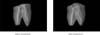
For each tooth pre and post-operative cross-sectional images were obtained by the micro CT (SkyScan 1072, Skyscan n.v., Belgium). Each tooth was scanned at 50 micron intervals. Approximately 300 cross-sectional images were obtained for each tooth11). Pre- and post-operative cross-sectional images of 1, 2, 3, 5, and 8 mm from the apex were compared. For each section, canal area and centering ratio were determined12). Centering ratio, reported by Calhoun and Montgomery, was calculated by the following formula13): (X1-X2)/Y X1 represents the maximum extent of canal movement in one direction. X2 is the movement in the opposite direction. Y is the diameter of the final canal preparation. To obtain the value of X1, X2, and Y canal area of the preand post-operative images were painted with different color. Then two images were superimposed after adjusting the opacity of preoperative image using Adobe Photoshop 6.0 (Adobe Systems Incorporated, USA). The difference of the opacity made superimposition possible. The difference of the color made the canal wall of the two superimposed images discernible. Removed dentin area and centering ratio were obtained by image software program (Sigma scan 1.20, Jandel Scientific. Corp., USA). For each tooth pre- and post-operative root canal volume from the furcation to the apex of the roots was calculated by three-dimensional image software (V-works 4.0, Cybermed Inc. Korea)14). Data was statistically analyzed by one-way ANOVA.
III. Results
All outcomes in the tables represent the mean ± standard deviation. Removed dentin area is shown in Table 1. At 8 mm from the apex, area of dentin removed by GT rotary file was significantly larger than that by profile .04 (p < 0.05).
Centering ratio is shown in Table 2. There was not a statistically significant difference at each compared level in centering ratio except at 3 mm level.
Pre- and post-operative root canal volume and the difference are shown in Table 3. Root canal volume increments were larger in Profile .04 taper group than in GT rotary file group but there was no statistically significant difference between the two groups.
IV. Discussion
Various techniques have been used to study the morphologic characteristics of human teeth. In this study, the preparation result of two types of Ni-Ti files currently used was evaluated by using micro CT. Bramante et al. compared pre- and post-operative root canal geometry with the method of horizontal tooth sectioning and reassembling the segment in the muffle system15). The Bramante technique was later modified and improved by other researchers16,17). Applying the Bramante technique, Berutti has introduced a new computerized method for a three-dimensional visualization of the root canal, before and after instrumentation. However, only midroot area reconstructed by five cross-sections could not provide sufficient data18). Blaskovic-Subat et al. combined actual tooth sectioning and computerized method and produced more accurate root and root canal model19). But tooth sectioning in these methods caused the loss of tooth material and incontinuity of segments. Thus the evaluation was restricted to predetermined level.
Recently developed micro CT has applications in many fields. This scientific tool has much potential in endodontic research because it is nondestructive and provides three dimensional images as well as quantitative data related to external and internal tooth morphology. In 1999, Rhodes et al. compared external and internal morphology of micro CT image and video-digitized images. They found a highly significant correlation between the micro CT and video areas20).
With the development of technology, the resolution of micro CT was improved remarkably compared to previous conventional CT. The resolution of conventional medical CT was in the range of 1 - 2.5 mm. So it could not give a meaningful data in the endodontic research. But the system "SkyScan 1072" in this study allows us to reach a spatial resolution of 5 µm corresponding to near 1 × 10⁻⁷ cubic mm voxel size, according to the manufacturer21). Such an improved resolution made the morphological analysis of the root canal system possible. The resolution of the pixel used in this study was 16.66 µm. Every third cross-sectional images, or at 50 µm intervals were obtained. Each image was composed of 1024 × 1024 pixels. Therefore voxel size was determined by pixel size (16.66 µm × 16.66 µm) and slice spacing (50 µm)22). Slice spacing was determined considering the convenience of data handling and time required to obtain the data. Technically, the highest currently achievable micro CT resolution in vitro ranges from 5 to 10 µm. However, slice thickness of 50 µm in the present study yielded an acceptable image quality because root canal anatomy changes only gradually in the long axis of the root6).
According to Table 1, there was no statistical difference at 1, 2, 3, and 5 mm level between two groups. But at 8 mm level, GT rotary file removed more dentin than Profile .04, which means that GT rotary file has more cutting ability over the orifice area than Profile .04.
To evaluate the canal transportation at predetermined level centering ratio was calculated in this study. The centering ratio is a measure of ability to maintain the original canal shape after canal instrumentation. According to the formula, centering ratio approaches zero as X1 and X2 become closer. Zero is an indication of perfect canal centering and no canal transportation23). There was a trend for GT rotary file to remain more centered in the canals in comparison with Profile .04 at all levels. Although at 3 mm level there was a statistically significant difference, this difference did not seem to have important meaning practically.
Once pulp structure was constructed three dimensionally from the cross-sectional images, root canal volume was obtained automatically by the software (V-works 4.0). The results of Table 3 represent the sum of mesiobuccal and mesiolingual canal volume. Because of the irregular pulpal structures connecting mesiobuccal and mesiolingual canal, it was difficult to deal with the volume of mesiobuccal and mesiolingual canal independently. It probably poses limits in interpreting the volume data because the instrumented and uninstrumented portion was regarded as a one. But the change of the canal volume after canal preparation has significance in itself. Unexpectedly, the amount of root canal volume change was larger in the Profile 04. In some degree this can be explained by the fact that mandibular human molars have much variation in the anatomy so that preoperative canal volume, the degree of canal calcification and the length from the furcation to root tip were different within specimens. And also according to the results of table 1, because removed dentin area by Profile .04 was a little larger at 1, 2, 3, and 5 mm level, the possibility can not be excluded that Profile .04 cut more dentin than GT rotary file group under specific level.
Recently Peters et al. assessed effects of Ni-Ti preparation techniques on root canal geometry by micro computed tomography. They concluded that while there were significant differences with respect to canal type, no differences were found between instrument types on changes in volume and surface areas, and canal curvature. This conclusion indicates that individual canal anatomy can have a great impact on post-operative canal geometry2,14).
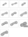
As presented in figures, the images provided with this method are dramatic, and their full potential for research has yet to be determined22). A useful visualization of the tooth was created by making the dentin transparent and the root canal system opaque24). With these images and dedicated software many interesting works will be done in the future. For example reconstructed tooth images will be useful to the students who learn the tooth structure and endodontic treatment for the first time. Visualization of filling material can show the quality of endodontic treatment and this will be helpful for the analysis of failure case3). Moreover a recent paper has introduced three-dimensional teeth model and virtual tooth drilling on computer and this simulation could serve as perfect educational tool for the students who desire to study the first step of an endodontic therapy25).
New method by micro CT and accompanying software can be used in the geometry-related study including comparison of the preparation effect by other types of files, the file size at which transportation take place, the direction of transportation, the file size at which destruction of apical constriction take place, canal center movement, the change of the canal curvature after canal instrumentation and so on.
CT imaging of teeth at the resolution of micro CT could never be used as a clinical technique because of the very high radiation dose that would be received by the patient. However, micro CT imaging is a powerful in vitro method in endodontic teaching and research3).
In conclusion, the use of micro computed tomography in evaluating root canal instrumentation has advantages in that it is nondestructive and provides three-dimensional images. In particular, the ability to image an internal structure allows the morphologic characteristics of root canal systems to be appreciated more easily. In this study, except the removed dentin area of coronal portion and the centering ratio at apical 3mm level, there was no significant statistical difference between GT rotary file and Profile .04 (p > 0.05, one-way ANOVA).
V. Conclusions
At 8 mm from the apex, area of dentin removed by GT rotary file was significantly larger than that by Profile .04 (p < 0.05). And at the other level (1, 2, 3 and 5 mm) there was not a significant difference (p > 0.05).
There was a trend for GT rotary file to remain more centered in the canals than Profile .04 at all levels. Especially at 3 mm level there was a statistically significant difference (p < 0.05).
In root canal volume increments after instrumentation, there was no significant difference between two groups (p > 0.05).
The method using micro CT and image software is effective for the quantitative evaluation of root canal instrumentation.


 XML Download