

 PDF
PDF ePub
ePub Citation
 Print
Print


INTRODUCTION
Damaged teeth are successfully restored using the manual lost-wax technique.1 In general, esthetic restorations are mostly used as fixed dental prostheses for metal-ceramic crowns and all-ceramic crowns, but metal-ceramic crowns are still used.234
The metal-framework of metal-ceramic crowns is fabricated so that the ceramic superstructure can be safely lifted, and manufactured through a manual build-up process. The metal-framework, which is the underlying structure of the metal-ceramic crowns, is an important substructure because it helps the ceramic remain safe and supportive.5
Marginal and internal fit are the most important features of fixed dental prostheses.67 Failure of marginal and internal fit can lead to secondary caries, periodontal problems, and pulpitis, causing failure of the prosthesis.891011 The margin of marginal fit that can be accepted clinically was reported as 90 – 200 µm.51213 Many researchers consider the optimal margin of marginal fit is within 120 µm.13
Recently, a dental computer-aided design/computer-aided manufacturing (CAD/CAM) system was applied to the dental field to improve the fitness and work efficiency.14 Most dental prosthesis is manufactured by an automatic method, so that the work burden of the dental technician can be minimized.15 This system was reported to be suitable for dental prosthesis manufacturing because it is possible to manufacture a large amount of prosthesis more accurately and quickly. CAD/CAM systems in the dental field can be divided into the following two categories:161718 Subtractive manufacturing is a process that mills a block, and additive manufacturing is a layer-by-layer method that is newly introduced. Subtractive manufacturing is both wasteful of materials and insufficient to reproduce fine details. However, additive manufacturing is being introduced as an alternative to subtractive manufacturing. It was shown that it is useful in the dental field because it can reproduce fine parts with a certain amount of materials.
A micro-stereophotography (µ-SLA) method of additive manufacturing has been developed.816 This is similar to the conventional digital light processing method, and a resinframework can be finely fabricated at a layer thickness of 30 µm by casting with a metal-framework. This single resinframework of nickel-chrome (Ni-Cr) alloy has been extensively studied and has been successfully evaluated clinically.816 However, there is a lack of research on the three-unit metal frameworks using Ni-Cr alloys.
This study evaluated the marginal and internal fit for three-unit metal frameworks made from subtractive and additive manufacturing. The null hypothesis is that no difference will be found between the marginal and internal gap of the three-unit metal framework fabricated from subtractive and additive manufacturing processes.
MATERIALS AND METHODS
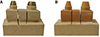
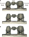
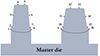
The three-unit master die used in this study was fabricated according to the existing literature.19 The three-unit metal framework abutment had a 360° chamfer margin, and the axial wall was prepared at 6° (Fig. 1). For fabricating the working die, twenty silicone-impression samples were prepared in two steps (Aquasil Ultra XLV and Aquasil Ultra Rigid, Dentsply DeTrey GmbH, Konstanz, Germany). Ten impressions were poured from Type IV stone (Fujirock EP, GC Europe N,V, Leuven, Belgium) to produce ten working dies. Ten impressions were poured from scannable stone (Everest Scan, KaVo, Biberach, Germany) to make ten scannable working dies. Twenty working dies were trimmed using a trimmer machine. Three-unit work dies were used to wax-up and scan the abutments. A hole was formed on the bottom of the abutment using a pindex machine (Perfect System, JaeMyung Corp., Gimpo, South Korea). The abutment was fixed using a double pin in the hole.
After applying a gypsum separator (Magic Sep, Talladium Inc., Valencia, CA, USA), the working die was supported with stone (Fujirock EP, GC Europe N,V). After final gypsum hardening, the two parts were cut so that the abutment teeth could be separated on the three-unit working die using a sawing tool (Fig. 2).
For the lost-wax technique (LW group), a die spacer (Nice Fit, Shofu Inc., Kyoto, Japan) was applied to the prepared abutment Type IV three-unit working dies. As one coating 10 µm thickness, the occlusal surface and axial wall were applied five times at a constant thickness of 50 µm. The marginal area was set to 0 µm without coating. The wax separator (Isolit, Degudent Gmbh, Hanau, Germany) was applied to the working die. Ten three-unit wax frameworks were fabricated using wax-up (Geo Wax; Renfert GmbH, Hilzingen, Germany) with the LW technique.
In this study, the frameworks for subtractive manufacturing (SM group) and additive manufacturing (AM group) were designed under the same conditions. The prepared scanned stone three-unit working die was scanned using a model scanner (Identica Blue, Medit, Seoul, Korea). The scanned stereolithography (STL) file was set to a thickness of 0.5 mm frameworks using dental CAD software (DentCAD, Delcam Plc., Birmingham, UK). The axial wall occlusal cement space was assigned to 50 µm and the margin area was set to 0 µm.
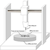
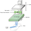
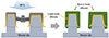
The prepared STL file was applied to a subtractive manufacturing machine (DWX-50, Roland DG Corporation, Shizuoka, Japan) (Fig. 3). The material used was a wax block (Vipi block wax, Pirassununga, Sao Paulo, Brazil), and it was produced by milling 10 three-unit wax frameworks. The same STL file was applied to the µ-SLA machine (Projet 1200, 3Dsystems, Rock Hill, SC, USA) for additive manufacturing (Fig. 4). Mounted ultraviolet (UV) curing resin cartridge was used (Visijet® FTX Green Resin, 3Dsystems).
The length of the resin support was set to 3 mm and 10 three-unit resin frameworks were printed. It was finally cured with a UV lamp for 10 minutes. The wax frameworks of the LW and SM groups and the resin frameworks of the AM group were buried using investment material (Formula1, Whip Mix Corp., Louisville, KY, USA) under the same conditions.
The mixing ratio was set to the manufacturer's recommended liquid/powder ratio of 22 mL to 100 g. The burn out process went through two stages: maintained at 450℃ for 30 minutes and then held at 900℃ for 1 hour. Therefore, the burn out was for a total of 2 hours and 30 minutes, and the wax frameworks and resin frameworks were then removed. The casting process used a centrifugal casting machine. A metal casting alloy (Verabond 2, Albadent, CA, USA) was melted with oxygen and gas and cast in a centrifugal casting crucible. The divesting of the investment material was carried out with 110 µm aluminum oxide (Basic Classic, Renfert GmbH, Hilzingen, Germany) and a 3 bar press to remove the buried deposit inside the three-unit framework (Fig. 5).
The prepared three-unit metal copings were injected with about one-third of the light-body (Aquasil Ultra XLV, Dentsply DeTrey GmbH) inside (Fig. 6). Then, the injected metal copings fit into a three-unit master die. A pressure of 50 N was applied uniformly using a pressure machine (Instron 3345, Canton, MA, USA) and maintained for 5 minutes before carefully removing the metal copings. The thin light-body was supported by using a heavy-body (Aquasil Ultra Rigid, Dentsply Detrey GmbH). The final silicone materials were hardened and then the silicone replica and three-unit master dies were separated. The separated silicone replica was cut into mesial and distal segments. The thickness of the light-body silicone was measured with a digital microscope at 160× magnification (KH-7700, Hirox, Tokyo, Japan) in 16 areas of the cut section (Fig. 7).
To investigate significant differences among the three groups, the normality test, Kolmogorov-Smirnov and Shapiro-Wilk test, were conducted but the normality was not satisfied. Measurement data were assessed by non-parametric Kruskal-Wallis H test and Mann-Whitney U-test (α = .05). The Mann-Whitney U-test and Bonferroni correction were used for post-testing (P < .05/3 = 0.016).
RESULTS
The lowest marginal gap (mean and standard deviation) for premolars and molars was 50.09 ± 34.76 µm in the SM group and the highest gap was 107.27 ± 61.33 µm in the AM group (Table 1). Among the internal gaps, the lowest chamfer gap was 61.43 ± 35.62 µm in the SM group and the highest gap was 238.16 ± 86.72 µm in the AM group. There was no statistically significant difference in the axial wall area (P < .117).
Table 2 shows the mean and standard deviation for each premolar and molar in the three groups. The lowest marginal gap (mean and standard deviation) of premolars was 51.44 ± 35.93 µm in the SM group and the highest gap was 99.06 ± 60.53 µm in the AM group. Marginal gap of molar was 48.73 ± 34.44 µm in the SM group, and the AM group had the highest gap of 115.48 ± 62.57 µm. The axial wall portion alone did not differ statistically between groups (P < .001).
For the internal fitness of the premolar, the chamfer gap of the SM group was the lowest at 63.30 ± 38.40 µm, and the occlusal surface of the AM group had the highest gap at 202.07 ± 58.46 µm. There was no statistically significant difference in the axial wall area (P < .246). In the molar group, the SM group showed the lowest chamfer gap of 48.73 ± 34.44 µm and the AM group had the highest gap occlusal area of 274.26 ± 96.31 µm. There was no statistically significant difference in the axial wall area (P < .173).
Table 3 shows the mean and standard deviation of the marginal spacing of the 8 and 9 (pontic) areas and the marginal spacing of the 1, 16 (non-pontic) areas. The lowest gap area was 24.40 ± 11.92 µm in the pontic area of the SM group and the highest gap area was 149.39 ± 42.30 µm in the pontic area of the AM group. All groups showed statistically significant differences between the pontic and nonpontic area (P < .001).
DISCUSSION
The results of this study rejected the null hypothesis that no difference will be found between the marginal and internal gap of the three-unit metal framework fabricated from subtractive and additive manufacturing processes. This is because it would affect the marginal and internal gap of the three-unit metal framework fabricated by subtractive and additive manufacturing methods.
Previous studies have analyzed the marginal fitness of fixed dental prosthesis made by using various methods,2021 including measuring fit by direct cementing to an abutment tooth model and cutting.22 Another study used a silicone replica technique in which the marginal area was popularized by considering the light body as cement, and then the surrounding area was formed using a medium or heavy body.2324 In addition, 2D or 3D images were acquired and measured by X-ray micro-computerized tomography.2526 Furthermore, a light body was considered cement when using a 3D scanner, and the thickness was measured using 3D software.27 In this study, the silicone replica technique was used to measure the marginal and internal gap of the prosthesis. This method of measurement was used because it preserves abutment teeth and prostheses and is currently the most popular measurement technique.
Data in Table 1 and Table 2 showed that the SM group, produced by subtractive manufacturing, had the better gap value, although there was no statistically significant difference found from that of the LW group. However, although the same STL file and application was used for the SM and AM groups, the marginal and internal gap was better in the SM group compared with the AM group. This might be explained by a difference between the milling process and the layer-by-layer process. In the subtractive manufacturing method, the wax frame is manufactured by milling where the end mill directly contacts the wax block according to a predetermined numerical value. However, the µ-SLA system used in the AM group is less accurate than the method used in the SM group because the resin-framework fabrication uses a non-contact UV light source in the liquid of UV photopolymer resin and because of unexpected UV light sources as the light source passes through the UV resin liquid.28 Therefore, both premolars and molars in the AM group showed a higher internal and marginal gap than in the LW and SM groups.
In Table 3, pontic of 1, 16 area and non-pontic of 8, 9 area were analyzed to determine the marginal gap in detail. The analysis showed that the marginal gap was larger in the pontic area of the AM group than in the other groups. The reason for this may be due to the shrinkage of the resin in the pontic areas. In addition, the other groups used wax framework and investment material whereas the AM group was fabricated using a resin framework.
In the SM group, it was considered that wax had a lower effect on shrinkage than in the other groups because a solidified milling exclusive wax block was used. In the present study, the three-unit showed different marginal gap values depending on the presence of pontic, and that the fit of the wax framework and the resin framework were different according to the compatibility with the investment material. In this study, the surfaces of the wax framework and the resin framework were poor. The wax is removed immediately during the burn-out process, but the resin framework appears to have a negative effect on the investment. The surface of the AM group was rough compared to the other groups.
The SM and AM groups have the advantage of repeated production based on the same data. However, the AM group had a larger gap compared with the SM group, although it can be manufactured faster than using the existing milling equipment, and the cost of materials can be minimized. In the future, the µ-SLA system might be useful in the dental field if it can provide values applicable to clinical use. The additional benefit of AM is that it can be used for mass production of multiple products as patients' prosthesis vary widely.
This study had some limitations. The three-unit metal framework was not a morphologically applicable model. It was also not an assessment of marginal and internal fit in a ceramic crown with a final ceramic build-up. In future studies, it will be necessary to make a final prosthesis that can be applied to clinical practice by producing a morphological master die, and to evaluate the best fit by using an investment material suitable for the resin framework. There are many types of additive manufacturing systems available. It is necessary to determine the optimal metal framework using a variety of systems.
CONCLUSION
The conclusions of the marginal and internal fit of LW group, SM group and AM group made with three-unit metal-framework are as follows. The AM group showed the largest marginal gap compared with that of the LW and SM groups, and the difference was statistically significant. Further study of the AM group is needed to determine its potential clinical application.


 XML Download