

 PDF
PDF ePub
ePub Citation
 Print
Print


INTRODUCTION
In many instances, oral implants provide ideal replacement of missing teeth. Although the overall implant outcome is favourable, implant-related mechanical and biological complications are still frequently encountered. One of the contributing factors that influence the longevity of implant prosthesis is dental occlusion. Uncontrolled occlusal forces can lead to implant overloading and detrimental stresses development.1 Strains beyond the physiological limit of bone can evoke bone loss around implants and eventual failure of the implant.2 Mechanically, excessive strains on implants can cause different failure types involving the implant, its components, or the prosthesis.13 As a result, it is reasonable to propose an occlusion scheme that will minimize the stresses applied on the implant, without compromising the function and the esthetics of the prosthesis.123
In the literature, several occlusion schemes were described for natural teeth.45678 Although they are similar in maximal intercuspation (MI), they vary significantly during excursion. The most commonly described occlusion schemes are canine-guided (CG) occlusion, group function (GF) occlusion, and balanced occlusion.4 CG occlusion occurs when the overlap between the maxillary and mandibular canine teeth disengages the posterior teeth during excursive movements.9 It relies on the anatomy and proprioceptive abilities of canine teeth.10 GF occlusion is described as multiple lateral occlusal contacts on the working side.9 The simultaneous contacts are thought to distribute occlusal forces.56 Balanced occlusion is distinguished with the presence of simultaneous contacts on working and non-working sides during excursion.9 However, due to the expected risks associated with balanced occlusion, there has been a recommendation to avoid this scheme.11 Another occlusion scheme described in the literature and has been observed naturally is the long centric (LC) occlusion, where many teeth maintain the contact in the initial stages of excursion, followed by CG occlusion at the later stages of excursion.12 These schemes are relevant as they have been commonly used to restore teeth and exist in the natural dentitions.13
Biomechanically, key differences exist between natural teeth and osseointegrated implants. The natural tooth root is retained within the alveolar bone by periodontal ligament (PDL), which absorbs and distributes forces applied on the tooth. Furthermore, the PDL maintains inherent mobility of the natural tooth.1 In addition, the PDL provides proprioception feature, which allows for protection against occlusal overload. On the other hand, PDL is missing between alveolar bone and implant, and the implant is directly anchored within the bone with a movement of 20 times less than natural tooth movement.1 Due to the lack of PDL, the proprioception around the implant is reduced.1 Therefore, due to the inherent lack of implant mobility and reduced proprioception, the implant and its prosthesis are prone to overloading. During normal mastication, teeth become compressed in their sockets, leaving the implant prosthesis in hyperocclusion.13 As a consequence of overloading, the implant may suffer from alveolar bone loss14 and mechanical complications, such as ceramic chipping, screw loosening, or components fracture.21516 To overcome the inherent limitations of implant prosthesis, occlusal considerations were discussed in the literature for the purpose of reducing the implant overloading.1718192021 An occlusion scheme specific to implant prosthesis is termed implant-protected (IP) occlusion.123 In light occlusion, the prosthesis should not be touching the opposing tooth. However, under heavy biting forces, the prosthesis should be in light contact as the natural teeth are intruded.1 In the excursions, there should be no contact on the implant prosthesis laterally. Instead, the lateral contacts should be maintained in the natural teeth. However, in order to provide objective recommendation, it is beneficial to validate the impact of different occlusion schemes. Therefore, the aim of this study is to investigate the effect of four different occlusion schemes and different excursive positions on peri-implant strains of a maxillary canine implant. The hypotheses are (1) there is an effect of occlusion scheme on peri-implant strains, and (2) there is an effect of the excursive position on peri-implant strains.
MATERIALS AND METHODS
Completely dentate maxillary and mandibular stone teaching models with maximum intercuspation occlusion were used. The right canine of the maxillary model was trimmed. The maxillary and mandibular models were replicated by laboratory silicone (Pinkysil Addition Cured Silicone; Barnes, Bankstown, NSW). Methylmethacrylate resin (Vertex Self-curing Resin; Henry Schein, Waterloo, NSW) was poured in the silicone moulds and heat flasked according to the manufacturer's instructions. Methylmethacrylate resin was selected because it's Young's modulus is relatively similar to human bone. The generated maxillary and mandibular resin models were articulated on a Hanau modular articulator (014503-000; Whip Mix, Louisville, Kentucky) using average values. The occlusion was rechecked for maximum intercuspation and lateral GF occlusion was achieved on both sides. Initial GF occlusion was selected as it allowed alteration of the occlusion scheme by modifying the canine palatal anatomy.
Implant drills were used to create an ideal vertical hole in the area of the maxillary right canine, which was slightly larger than the implant diameter. The hole was filled with freshly mixed methylmethacrylate resin and an implant (5.0 mm diameter, 13 mm long Branemark Mk III external hex implant, Nobel Biocare) was inserted in the hole simultaneously. The model was returned to the heat flask to complete the curing of the resin.
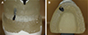
Four different crowns were fabricated for the purpose of achieving four different lateral occlusion schemes on the right side. A wide platform prefabricated titanium abutment (Branemark Snappy Abutment, Nobel Biocare, Macquarie Park, NSW, Australia) was attached on the implant and torqued to a recommended value of 35 Ncm. A cross-pin design was used to avoid screw access in the area of loading and to allow ease of changing the canine crowns while maintaining the same loading set-up (Fig. 1).
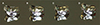
The abutment was scanned by 3Shape scanner (3Shape D-640; Wieland-Imes, Pforzheim, Germany) and each crown was digitally designed to represent a defined lateral occlusion scheme. The applied lateral occlusion schemes were: (1) CG occlusion, where the overlap between the maxillary and mandibular canines evokes immediate disclusion of the rest of the dentition upon excursion; (2) GF occlusion, where all the teeth, including the canines, are in contact during excursion; (3) IP occlusion, where the contact between the maxillary and mandibular canines exists only at maximal interscuspation, but not in excursion; and (4) LC occlusion, where the occlusion is similar to GF occlusion for the first 1 mm of excursion, after which it changes to CG occlusion. The digital fabrication method was followed to ensure the differences between the crowns were restricted on the palatal guiding surface. A resin pattern for each crown was 3D printed, fitted on the abutment, and verified on the articulator. Whenever necessary, minor adjustments were performed by wax. The most apical part of the crowns was broadened to allow incorporation of the cross-pin. All the crowns were invested and casted in cobalt-chromium alloy (Fig. 2). After polishing the crowns, the occlusal schemes were re-checked on the articulator.
Three loading points were marked on each crown. The first point was on the cingulum and corresponded to the maximal intercuspation (MI) position. The other points were 1 mm and 2 mm buccal from the MI, which corresponded to the loading after 1 mm and 2 mm excursion, respectively. The marking provided consistent reference loading points prior to loading for each test cycle. The three points were selected to allow simulation of occlusal contacts that occurred during functional and parafunctional range of movement.2223
One rectangular stacked 45-degree rosette strain gauge (Vishay Precision Group, Raleigh, NC, USA) was attached with cyanoacrylate resin (M Bond 200 adhesive Vishay Micro-measurements, Raleigh, NC, USA) to the mid-buccal crestal area overlaying the implant body. The gauge was composed of three strain foils: horizontal, vertical, and diagonal foils. The maxillary model was mounted on the Material Testing System platform. The model was not moved until the completion of the loading. A linear variable differential transformer (LDVT) horizontal arm (Solartron, QC Systems Pty Ltd., Vic, Australia) was placed against the most convex area on the buccal surface of the crown to measure lateral movement under loading. The purpose of the LDVT was to detect any displacement of the crowns during loading. The strain gauge was connected to Wheatstone data acquisition system (National Instruments Corp., Austin, TX, USA). The LDVT was attached to a signal conditioning units (Solartron Metrology Pty, VIC, Australia). Eventually, the data recorded from each measuring tool were monitored by computer software (Lab View 7 Express, National Instruments Corp., Austin, TX, USA).
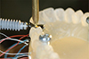
For each crown, a computer-controlled precision universal testing machine (MTS 810 Materials Test System; MTS Systems Corp., Eden Prairie, MN, USA) was used to apply repeated vertical static load of 140 N at the three marked points (Fig. 3). A 140 N load was chosen as it fits within the physiological load range during mastication.1424 Each crown was cycled 10 times to maximum load at each loading site. Therefore, a total of 30 readings were generated for every lateral occlusion scheme.
For each loading condition, the strain generated from each gauge foil (vertical, horizontal, and diagonal) was recorded. Subsequently, maximum and minimum principal strain values were calculated for each loading according to the following equations:


where ε1 is the horizontal gauge strain, ε2 is the vertical gauge strain, and ε3 is the diagonal gauge strain.
The shear strain was subsequently measured by calculating the difference between the maximum and minimum principal strain values:
The average shear strain and standard deviation were calculated for the 10 readings of each crown and loading site. The generated data were tested for normality using the Shapiro-Wilk test. The effects of crown morphology (CG, GF, LC, IP) and loading site (MI, 1 mm, 2 mm) were evaluated and the interactions between them were investigated by the two-way analysis of variance test followed by Tukey post hoc test at a significance level of 5%. The statistical analysis was performed via SPSS software package (IBM SPSS Statistics, version 22, SPSS Inc., Chicago, IL, USA). The shear strain values for each crown were plotted in a box and whisker diagram.
RESULTS
For all the crowns and excursive positions, the lateral displacement did not exceed 70 µm. There was no significant influence of the different occlusion schemes and excursive positions on the lateral displacement. Therefore, major crown displacement that could influence the strains measurements was not observed in any loading condition.
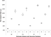
The shear strain data indicate that the occlusion scheme and the excursive position had effects on localized peri-implant strain magnitude. However, greater impact was detected from altering the excursive position than from altering the occlusion scheme. Table 1 summarizes the outcome of the average strain gauge values and standard deviations. For all the occlusion schemes, it is clear that as the excursive position moves buccally, the peri-implant strains increases (Fig. 4).
At MI, there was a significant difference among the occlusion schemes (P < .005). This difference existed among all the groups. GF was associated with the least strains, followed by IP, CG, and LC. At 1 mm, a similar pattern was observed where GF was still associated with the least strains. This was followed by IP, CG, and LC (P < .005). However, the difference was not significant between GF and IP (P = .65) and between CG and LC (P = .32). At 2 mm, the difference was significant between them (P < .005). GF had the least strains, followed by CG, LC, and IP. A significant difference existed within the different schemes, except between the IP and LC occlusions (P = .16). Overall, the outcome reflected that at the earlier stages of excursion, GF and IP were associated with the least strain values. However, as the excursion increased, the strains generated from IP became considerably high.
Regardless of the occlusion scheme, as the excursion increased, the peri-implant strains increased linearly. The strain pattern for the different locations was similar for all the occlusion schemes. For all the schemes, the difference in peri-implant strains within the different positions was significant (P < .005). The 2-way analysis of variance test revealed that there was a significant interaction between the occlusion scheme and the site of loading. The schemes that had less strain values at the MI position tended to have less strain values for the rest of the positions.
DISCUSSION
This study confirms that variation in occlusion scheme and excursive position influences the peri-implant strains. Thus, the hypotheses that the peri-implant strain magnitudes would be influenced by the occlusion scheme and the excursive location were accepted. Any functional implant is subjected to axial and non-axial forces. Axial forces are preferred as they place the peri-implant bone, implant components, and prosthesis under compression. In addition, the forces are evenly distributed within the peri-implant bone.131516 On the contrary, the non-axial forces are associated with localized stress concentration 1516 and can eventually evoke greater peri-implant strains.14 Much of the peri-implant bone strains will be in the crestal region, which is more susceptible to resorption.1516 In this investigation, the occlusion scheme was altered by modifying the canine palatal contour. Furthermore, varying the site of load application simulated implant crown loading in maximal intercuspation and excursive positions. It is very clear from this study that the palatal morphology and the excursive position can influence the peri-implant strains, which are most likely related to altering the proportion of axial and non-axial forces on the implant. Applying forces on inclined morphology was proven to increase the non-axial forces and the bending moment applied on the implant and the crown,219 as opposed to applying forces on flat surface. As the inclination increases, the lever arm between the point of load application and the fulcrum point at centre of implant increases, which will eventually accentuate the torque. In addition, the non-axial forces will increase by lateral loading of the implant crown. As the occlusal forces move laterally from the implant centre, the implant and the relevant components will be subjected to additional flexion and torqueing.20
Tooth morphology plays a considerable role in occlusion. This is particularly evident for the canines due to their location in the corner of the arch, which allows them to control the eccentric movements and the pattern of lateral contacts.410 As an effect of altering the canine morphology, the lateral occlusion scheme can range from CG occlusion to GF or IP occlusions. CG and LC occlusions are associated with greater overlap between the maxillary and mandibular canines to allow for posterior teeth disclusion.17 This has been established in this study by increasing the incline of the canine palatal contour. As a result, these occlusion schemes were associated with greater peri-implant strains at MI and the early stage of excursion. On the contrary, shallow canine palatal morphology, such as in GF or IP occlusions, tends to have less strains at MI and the early stage of excursion (1 mm). The outcome of this study confirmed the observation of Rungsiyakull et al., who found that premolar implant crowns with steeper cusp inclination had greater peri-implant strains than crowns with shallower cusp inclination.19 However, as the excursion extends to 2 mm buccally, a different pattern was observed, and the IP occlusion had experienced a considerable localized increase of peri-implant strains. Although IP occlusion is thought to evoke less peri-implant strains, this was not consistently observed through the whole excursion path. This reflects the complexity associated with dental occlusion and palatal contour that can cause variation in the steepness along the excursion path. The crowns were constructed to test the effect of bucco-lingual morphology, but the different crowns exhibited different mesio-distal morphology, which might have had effects on the results. Differences in the mesio-distal morphology can cause the load pointer to shift down the ridge mesially or distally. While it may appear minimal, it will lead to strain fluctuation in experiments due to additional torsional strains being superimposed. In addition, although the differences between the occlusion schemes are statistically significant, it is very difficult to speculate the clinical impact of such difference. The high statistical difference can be due to repeating the load application on single crowns. As a result, a low standard deviation was observed. Additional experimentation should evaluate multiple crowns in each scheme.
In order to simulate the natural pattern of occlusal contacts, each crown was loaded in MI and two excursive positions. These were adopted because it was thought to be clinically relevant and reflect the functional loading on the crown, as several reports pointed that functional occlusal contacts occurred within a range of few millimetres.2223 Functional movements, such as chewing and physiological grinding, occur naturally within 0.5 mm from the MI position.78 The excursive range from 0.5 mm to edge-to-edge position is used during parafunctional activities. Therefore, the experiment covers the possible occlusal force occurrence during functional and parafunctional range of activities. It is very clear that regardless of occlusion scheme, as the excursion increases, the peri-implant strains increase as well. At MI, the force is directed parallel to the implant which will render the force of compressive nature. However, when the excursion occurs, the force direction will shift buccally, producing a coupling force to the centre of the implant and resulting in a larger bending moment1521. The increase of peri-implant strains in the excursive positions illustrates the negative consequences of localized stresses during parafucntional activities. It is likely that the implemented occlusion scheme is a less important for implant overloading than the presence of parafunctional activities. This is in accordance with a clinical study that reported a direct relationship between bruxism and increased implant prostheses complications.18
Contrary to the occlusion scheme, the excursive position has a greater impact on peri-implant strains. This indicates that the location of the load is much more significant in strain development than the palatal contour of the crowns. Therefore, altering the occlusion scheme for the purpose of changing the lateral contact pattern is more important than modifying the crown morphology and cuspal inclination. While this study had loaded all the crowns in all the excursive locations, the load might be different in clinical situations. From the clinical perspective, the canines in CG occlusion and LC occlusions are be the only teeth subjected to lateral forces in excursive positions.9 On the other hand, in GF occlusion, the lateral forces are distributed between the canine and the rest of the posterior teeth on the working side.9 An earlier study had reported that implant prostheses with GF was more comfortable than CG over a period of few months,17 which may be attributed to less restricted mandibular movement.5 While it is attractive to assume that GF is a safer occlusion, other investigators have reported increased chance to grind patients' teeth in eccentric positions. This has been observed by elevated EMG readings of masticatory muscles and increased condylar displacement with GF occlusion.56 CG occlusion exhibits a protective mechanism from the proprioceptive feature of canine teeth. However, whether the proprioceptive mechanism will offset the negative effect of palatal steepness is yet to be determined. Nevertheless, IP occlusion will be safer for the implant due to the absence of lateral occlusal contacts. For implant prostheses, several authors suggested using the natural teeth for occlusion guidance and alleviation of occlusal contacts on the implant prosthesis during excursive movement.120 This is envisioned to minimize the nonaxial forces on implant components and reduce the risk of mechanical complications through micromovement or flexure.20 Although IP is likely to be beneficial in eliminating lateral contacts on implant restoration, utilizing this scheme for anterior implant restoration may result in shallow morphology and shortened clinical crown that can hinder the dental esthetics.
A laboratory study is not sufficient to draw a definite clinical conclusion. A recent systematic review did not confirm the superiority of any occlusion scheme for teeth or implant prostheses.11 In a retrospective study, Kinsel and Lin evaluated the effect of lateral occlusion on implant-supported prosthesis complications. The included dentitions that had either CG or GF occlusion. Patients with GF occlusion had significantly greater chance of ceramic chipping than those with CG. However, the investigators did not relate the ceramic chipping solely to the occlusion scheme. In addition, they have reported more critical factors, such as bruxism and opposing implant prosthesis. On the other hand, several authors have reported there is no specific occlusion scheme that should be implemented for implant restorations. Instead, the lateral occlusion scheme for implant prostheses can mimic the the occlusion scheme on tooth supported prostheses.113 As a result, no specific occlusion scheme will be selected for all implant prostheses.
While this study has the advantage of simulating a clinical scenario, it has some limitations. For example, a true representation of natural cortical bone and trabecular bone is impossible in a laboratory study. This experiment assumes isotropic mechanical behaviour of bone. However, bone is inhomogeneous due to the variations in cortical bone thickness and trabecular bone porosity. As a result, variation in bone quality may react differently to occlusal forces.14 In addition, laboratory experimentations assume complete implant integration, which does not represent actual implant osseointegration.
CONCLUSION
Within the limitations of this preliminary study, it can be concluded that the occlusion scheme and the excursive position influence the peri-implant strains. According to the present experimental set-up, it appears that the impact of eccentric position is greater than that of the occlusion scheme. Implementing an occlusion concept that reduces the occurrence of occlusal contacts in excursive positions is preferable to reduce the strains within the peri-implant region.

 XML Download