

 PDF
PDF ePub
ePub Citation
 Print
Print


INTRODUCTION
Prosthetic rehabilitation of a totally edentulous mandible with an overdenture retained by two or more implants is a highly predictable treatment, with the implant success and survival rates above 95.5%.12 Compared to a conventional full denture, this treatment also provides high levels of satisfaction, comfort, and quality of life to patients.3456
McGill's International consensus7 and York8 established that two interforaminal location implants are sufficient, and the minimum option, to retain an overdenture with good stability and masticatory function. Numerous and different clinical and laboratory studies show that the option of two implants placed at canine level is the most common design to retain a mandibular overdenture. However, another distribution of the implants is possible.910 Bone availability factors can oblige the clinician to place the implants next to the mandibular symphysis (at the lateral incisor level) or at the premolar level, where it is more likely that at least 1 mm more bone can be maintained at the buccal and lingual walls than at the canine level. It has been reported that the long-standing mandibular edentulous ridge undergoes accelerated bone loss especially at the labial side of canine areas, which significantly reduces the ridge width in canine areas.11 Likewise, biomechanical considerations related to the stress transferred to the peri-implant bone and the implant/attachment complex during movements of the overdenture may make it necessary to place the implants more distally, at premolar levels, or to combine one anterior implant and the other posterior contralaterally. Currently there is an insufficient scientific evidence available concerning the influence of any of these implant locations on the survival or complications of the overdenture Locator® attachment system. Nevertheless, the Locator attachment is only one of the numerous attachment systems used to retain implant-supported overdentures. However, all attachment systems including stud, ball, magnetic, and bar attachments provide higher levels of satisfaction, safety, masticatory efficiency, and quality of life to patients compared to the use of a conventional denture.121314 In addition, numerous clinical and biomechanical studies have found differences when assessing and comparing the use of stud, ball, and bar attachments in terms of different parameters, including retention strength, resilience, progressive retention loss, and replacement/activation of attachment retention inserts and periimplant bone stress.151617181920212223 Meanwhile, although the degree of patient satisfaction does not seem to depend on the attachment retention system of the overdenture,132425 Locator® attachment is a stud, self-aligning attachment system, widely used for its simplicity of use, variable retention capacity, resilient retention, and compensation of implant disparallelism. However, like other attachments, it is not free from mechanical complications associated with the loosening/fracturing of the screw and premature change of the insert plastic patrix due to retention loss.15172627 Even so, very few data are available regarding the concentration/distribution of stress/strain in the patrix/matrix of these attachments and even fewer referring to the influence of different implant/attachment locations and of the occlusal loading application site.1628
During functional masticatory activities and clenching and grinding parafunctions, complex occlusal forces of different intensity, location, and direction occur. These forces are transmitted to the overdenture, implant/attachment system and peri-implant bone. The stress/strain resulting from the occlusal load has been extensively evaluated in implants and peri-implant bone but not in the Locator attachment components. With two implants placed at lateral incisor level and unilateral posterior load, lower stress is reported in Locator attachments compared to the ball system16 and higher stress in the vestibular area at the abutment/nylon interface with anterior vertical load in a model with two interforaminal implants compared to 3 or more implants.28
Also, although under discussion, bilateral balanced occlusion criteria are often the occlusal scheme recommended for an overdenture.293031 However, empirical clinical practice shows that this is not always the case, with a large number of dentists completing an overdenture treatment with other criteria or with a random occlusal contact distribution. Such a decision can change the distribution/concentration of stress/strain in the patrix/matrix attachment and plastic component of the Locator attachment, leading the attachment complications and retention loss, thus increasing the frequency of replacement. Although higher retention loss is reported with different attachment types19 and non-axial load,3233 the available information on the effect that the application site and occlusal load distribution relative to the different location of the two implants may have on the plastic component wear or on the attachment complications for higher stress is not conclusive. More data are needed to enable practitioners to know which is the implant and occlusal loading location that favors the best biomechanical environment and thus make appropriate decisions. In accordance with this, the aim of this study is to evaluate the effect of four different locations of the two implants of a mandibular implant-supported overdenture on the distribution stress in the Locator attachment system using the finite element method, to evaluate the stress transferred to the Locator attachments during occlusal loading at different application sites, and to give dentists a comparative insight into the influence of these factors.
MATERIALS AND METHODS
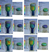
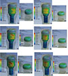
Three-dimensional finite element models were created to evaluate the stress distribution in the Locator attachment system for a mandibular overdenture retained by two implants. An arch structure was modeled to simulate the symphysis and body of an entirely edentulous mandible with the following dimensions: 60 mm mandibular body length from the middle line, 20 mm inferosuperior height, and 12 mm bucco-lingual width. The dimensions of the employed arch are similar to those of a real mandible since they are the average of the measurements of three jaws from the Department of Anatomy of the Faculty of Medicine of Oviedo. Therefore, the positions of dental implants and other elements correspond to those in a real mandible. Bone quality type 2 was assumed in the symphysis and type 3 in the mandibular body according to the Lekholm and Zarb classification34 and 2 mm thick cortical bone surrounding the cancellous bone. In addition, a threaded implant was modeled by using as a reference the geometry of a Stark D Active (Sweden&Martina, Due Carrere, Italy) internal connection implant, 4.2 mm body diameter and 10 mm length. Furthermore, a self-aligning attachment brand Locator (Zest Anchor Inc., Escondido, CA, USA) was modeled with abutment (matrix) of 4 mm gingival height and metallic cap with nylon insert (patrix). The abutment was screwed to the implant, and the patrix was attached to the overdenture.
The overdenture was a superstructure made of acrylic resin, 10.7 mm high and similar in shape, width, and length to the jaw bone. Four different finite element models were created. The model named “Implants at Laterals” simulated an overdenture retained by two implants placed at lateral incisor level and with a center-to-center separation of 15 mm. In the “Implants at Canines” model, the centers of the two implants were separated by 27 mm. In the “Implants at 2nd premolars” model, the distance between centers was 53 mm (26.5 mm from the mandibular midline). In the “Crossed Implants” model, one implant was placed on the left side, 13.5 mm from the midline (canine level), and the other in the contralateral arcade, 26.5 mm from the midline (2nd premolar level). The distances between implants were calculated according to the mesio-distal length of natural tooth crowns due to the great variability in the situation of two implants for a mandibular overdenture recorded in the literature. In follow-up studies, the majority of the implants were placed interforaminally.35 Biomechanical studies place implants at the level of laterals, 7 – 8 mm from the mid-line1636 or 13 mm intercenter9; however, the majority situates them at the canine level, separated by a range of 20 – 28 mm92837 while at the premolar level, the distance was 42 mm.9
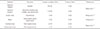
The jaw bone and all the materials used in these models were considered to be linearly elastic, homogeneous, and isotropic. Values for elastic moduli and the Poisson ratio of the bone and different materials were taken from published data,92238 Table 1. A continuous bone-implant interface, flawless and with 100% oseointegration, is assumed. All other interfaces between the rest of the different materials and structures were also assumed to be continuous (abutment-implant, abutment-patrix, and patrix-overdenture). Moreover, a passive fit without friction was assumed between the overdenture and the jaw bone without gingival mucosa interface.
In the four models, a vertical occlusal bilateral or unilateral static load of 150 N was applied under six different loading conditions. The unilateral single load (150 N) was applied at midline, left canine level, and 1st left molar (10 mm from the distal implant) and combined at midline (40 N) and 1st molar level (150 N). The bilateral load was applied at the level of the 1st molars (75 N on each side) and also combined with 40 N at midline. In the dental literature, a wide range of variability in the magnitude of occlusal loading is reported. This variability also occurs in finite element studies, where loads are reported in a range from 15 N39 to 250 N40, but more frequently 100 N9161725, and in others 150 N.414243 The data for von Mises stresses were produced numerically and the stresses in the finite element analysis were color-coded to allow for the comparison of the biomechanical differences between models.
All elements were modeled with Pro/Engineer Wildfire (Parametric Technology Corp., Needham, MA, USA) software computer aided design. The finite element models were created and meshed using Ansys 11.0, a commercial 3D finite element software (Ansys Inc., Canonsburg, PA, USA). In order to generate the meshes, the following four different kinds of element were employed: 3-D 10-Node Tetrahedral Structural Solid, 3-D 20-Node Structural Solid, 3-D 8-Node Surface-to-Surface Contact, and 3D Target Segment. As a result, the smallest model had 844,000 nodes and 97,003 elements while the largest model had 964,132 nodes and 108,802 elements.
RESULTS
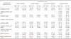
Table 2 shows the von Mises stress in the Locator attachments (abutment and patrix insert plastic) for each model and occlusal load application point. In all models, when unilateral load was applied, the highest stress values were recorded on the load side attachment with some exceptions. The attachment abutment (matrix) shows a level of stress about ten times greater than that registered at the plastic element (patrix), regardless of the load side and model. The worst biomechanical environment for attachments occurs in the lateral incisor level implants model especially with unilateral posterior load, midline load, or both combined. The crossed-implant model is the next worst in terms of biomechanical environment especially when a unilateral load is applied on the left side. However, in this model, the right side unilateral load (on the side of the more distal implant) shows a better biomechanical behavior in the attachments compared to the load applied on the left side.
In no model does the application of bilateral posterior load, combined or not with midline load, change the trend of much greater stress on the attachment abutment (matrix) compared to the insert plastic patrix. However, some models register a symmetrical stress distribution on both sides while in the other models, the stress distribution is not symmetrical. Overall, with a bilateral load, the best attachment biomechanical environment occurs in the 2nd premolar level implant model.
With minor variations in all models and regardless of the occlusal load location, the attachment abutment (matrix) stress is located and distributed mainly in the threadless area, dissipating laterally and toward the conical connection and first threads. In the insert plastic patrix, the stress is located in all models and load situations in the most coronal surface and the lateral areas near the free edge (Fig. 1 and Fig. 2).
DISCUSSION
Using 3D-Finite Element Analysis, this study evaluates the stress distribution in the Locator attachment components in mandibular overdentures retained by two implants at different locations subjected to unilateral or bilateral occlusal loads applied at different points. Even though the Locator attachment system is a very common prosthetic restoration design in routine clinical practice, very few studies in dental literature report stress levels and distribution in it, in contrast to the numerous studies evaluating the peri-implant bone stress. The combined effect of occlusal load and implants at different locations in the Locator attachments is not assessed or compared in any study. The only thing reported is lower stress in the attachment abutment (matrix) in canine location implants and with posterior unilateral load compared to anterior.28 This result disagrees with the data from this study, which, for a similar model and unilateral load, showed lower stress values in the patrix and matrix as the load application site became more mesial. This result can be explained by differences in the lever arm length of the applied load and increased bending moments coupled to the overdenture rotation movement as is noted in overdentures with 3 or 4 implants.28 However, there is an agreement regarding the stress location on the vestibular surface of the abutment/plastic patrix interface28 and on the occlusal plastic patrix surface with lateral incisor location implants.16 This finding shows that the locations mentioned may be those with greatest insert plastic patrix wear, favoring retention loss and the need for periodic replacement of this insert plastic. In the present study, this complication can occur in any of the four models, since the stress location in the plastic patrix is a constant, being independent of the model and occlusal load location. However, although better clinical results with no complications have been reported in locator attachments in 2-implant overdentures after 11 months compared to ball and bar attachments,15 in other studies19 the change of the plastic insert due to retention loss was the most frequent prosthetic complication of the locator attachments compared to Dal-Ro® and O'Ring® ball ones. Likewise, it should be noted that the wear of and damage to the locator attachment depend not only on the loading but also on the positioning conditions of the implants. Other factors may exert an influence such as type and direction of dislodgement force, the ridge anatomy, implant angulation, thickness of the mucosa, frequency of insertion, and removal of the overdenture by the patients. Hence the influence on the retention locator attachment has been recorded in vitro with various types of nylon inserts, as has the influence of repeated denture insertions and removal and the lowest retention with lateral dislodging force183344 and also the negative influence of implant angulation on the retencion force of the locator attachment system,214546 independently of the blue, pink or clear plastic insert used.47
It has also been found that the periimplant bone response to a unilateral occlusal load with much higher stress values on the load side compared to the contralateral side, as related in several articles,9162228434849 the data obtained show that the attachment stress both in the abutment and plastic patrix behaves similarly regardless of the overdenture implant location. A unilateral occlusal load rotates the denture base around a sagittal axis of variable location and moves it toward the unilateral load side, thereby increasing the stress and strain in the complex attachment, implant, or bone. There is a lack of studies to compare this effect in the locator attachment components, but the influence of the insert male type with a non-increase of peri-implant bone strain distal to an inclined implant when red nylon inserts were used has been reported with regard to peri-implant bone with uni or bilateral load.49 In this context, for each model and for each load application site, this study data shows a substantially lower peri-implant bone stress (unpublished data) compared to the stress supported by the plastic insert and the abutment. The abutment and the nylon insert would act as a resilient damper system, favoring the transmission of less stress to the peri-implant bone and thus preventing the loss of crestal bone around the implants. Since this effect in different finite element and extensiometric studies is related to the mechanical properties of the patrix/matrix materials,2237445051 differences are reported depending on the ball attachment type, plastic type, and applied load.374950 It has also been reported that an increase in stiffness of the plastic insert in a stud attachment led to an increase of the periimplant bone stress2251 while in a previous study comparing rigid and resilient ball attachments, the highest periimplant stress was recorded with the resilient ones.41
Likewise, the practical clinical consequence of the highest stress in the patrix and matrix of the attachments on the ipsilateral side with unilateral load would be increased wear and frequency of replacement of the plastic patrix, a higher frequency of deformation, or fracturing of the abutment (matrix). This may occur when the dentist completes a patient's treatment with a mandibular overdenture with an inadequate occlusal adjustment with an occlusal load predominantly on one side. These complications are most likely to occur with implants located at lateral incisor level with unilateral posterior load of all the possible locations for the two implants in the jaw.
The situation of diagonal or crossed implants for a two-implant overdenture is not very frequent in clinical practice although it is a reported option for conventional and implant-supported overdentures.5253 With this position of the implants/attachments, the denture base has an anterior retention/support and another posterior retention/support in addition to a wide and oblique rotation axis of anteroposterior direction. Thus, for any load application site in the denture base, shorter lever arms are set in comparison with two attachments at the canine level, which are also countered either by the anterior or posterior anchorage. All this could favor prosthesis stability, achieving a better biomechanical environment and providing greater patient comfort and safety than an overdenture with 2-implants in the anterior region. Confirmation is required with clinical studies. In any case, in the crossed-implants case, the lowest probability of attachment complications occurs with a unilateral load applied on the side of the most distal implant. In addition, data from this study suggest that occlusal adjustment achieving posterior bilateral contacts or combined with mid-line contacts with some exceptions favors the non-appearance of these complications especially when implants are placed at second premolar level or in the crossed implants model. In any case, the stress magnitude recorded in the attachments of this study shows that abutment (matrix) complications could occur if the stress values exceed the 860 MPa yield strength estimated for the most widely used titanium alloy in dentistry (Ti-6Al-4V) or 600 MPa fatigue limit.54 However, although the stress in all models is located and distributed mainly in the abutment threadless area and, in some models, is higher than 860 MPa, which could deform or break the abutment the spread of stress to weaker abutment areas such as the cone and threads makes it more likely that the attachment will loosen or fracture. This complication is observed in clinical practice and reported with variable frequency in reviews and clinical studies.15172627 In this study, in agreement with stress distribution in the attachment thread, this complication is most likely to occur in contralateral attachments with unilateral load mainly at canine level. These data suggest avoiding unilateral contacts and/or lateral guidance in the occlusal adjustment of mandibular overdentures retained by two implants.
Future biomechanical studies should be carried out to replicate, or not, these results. However, it would be more advisable to carry out longitudinal clinical studies (prospective or retrospective) with a suitable design to evaluate the association of the implant situation and the application load site with the complications in the Locator attachments and in the bone around the implants and also to compare this with other attachment systems to allow clinicians to choose the most appropriate one.
Finite element analysis is a widely employed method in dentistry to estimate the stress/strain distribution in the peri-implant bone, prostheses, and prosthetic components in many diverse situations. However, with a mathematical and computational model, it isn't possible to model and simulate all prosthetic restoration, ground support, masticatory function, and oral environment design features and responses. Therefore, it is necessary to assume a number of simplifications related to material properties, geometry, interface, and load and contour conditions, which sometimes limit the data to not correspond exactly to the clinical results. For this reason, clinical studies are always necessary to validate the results of a finite element analysis.
So when this method is used, a qualitative comparison between models and variables is recommended rather than a quantitative one. Material properties and structure geometries have a great influence on the stress/strain distribution, but as in other similar studies,91628 it was assumed that all materials were homogeneous and linearly isotropic. It was also assumed that the interfaces between different materials and structures were continuous with a passive fit without any friction; in clinical reality, these assumptions are not always true, being a possible limitation.
A curved overdenture of uniform height and thickness was modeled as a jaw of similar uniform morphology but different dimensions without gingival mucosa interface, condylar anchorage, or other restrictions on movement. Although these factors can be the limitations, they will not influence the attachment stress distribution because these structures remained constant for all models and loading. In any case, the main dimensions of the arch are similar to a real mandible and therefore, the position of dental implants and other elements correspond to the ones they would have in a real mandible. The simplified model allows a quicker computation of all calculations required for the finite element models. The real model does not add any important information but only implies greater model complexity. In accordance with Liu,28 the nylon (polyamide) was a plastic insert of the matrix; PMMA (polymethylmethacrylate) was used in another study.16 Although the elastic properties are not very different, the differences in stiffness between the two materials may influence the attachment/implant/bone system stress distribution. Several studies show the influence of an insert plastic patrix of varying degrees of stiffness on the stress transfer to the attachment/implant/bone system or residual ridge.22363744 This may be a limitation or should be taken into consideration. During chewing, complex force patterns of variable magnitude and direction take place from one area of the mouth to another and between subjects, which are impossible to mathematically reproduce and simulate. In this study, a 150 N vertical force is applied, which is considered an occusal load very close to masticatory forces and in agreement with other overdenture finite element analysis studies.414243 Also, since contacts between all teeth are established during mastication and an overdenture could combine straight and angled implants or abutments, a solely vertical load design of unilateral or bilateral posterior location may be a limitation that the clinician should consider when comparing and discussing the clinical implications of a finite element analysis. Although unilateral and bilateral occlusal load combinations are cited in some studies,916232855 the dental literature concerning overdenture and finite element analysis reports a great variability in the direction, application site, and magnitude of occlusal loads, which per se is a limitation for the comparison of results; it is therefore necessary to standardize these factors.
CONCLUSION
In accordance with the results and within the limitations of a finite element analysis, this study indicated that the overdenture model with lateral incisor level implants is the worst design in terms of biomechanical environment for the attachment components. With some exceptions, bilateral load favors a more uniform stress distribution in both attachments compared to much greater stress registered with unilateral load in the load side attachments. Regardless of the implant positions and the occlusal load application site, the stress transferred to the plastic patrix is much lower than that registered in the patrix. Dentists should take these data into consideration in the overdenture occlusal adjustment.
 XML Download