

 PDF
PDF ePub
ePub Citation
 Print
Print


INTRODUCTION
Porcelain-fused-to-metal (PFM) dental crowns, used mainly for aesthetic restoration, are being adopted widely for permanent restoration using the lost-wax technique.123 The usual method of producing PFM crowns is to wax a prepared “stone die” and then make a metal framework from it by going through the steps of investment, burnout, and casting. In turn, the metal framework goes through opaque, dentin, and glaze firings.4 An important aspect here is the bottom structure; if the metal framework is not stabilized at its base, its upper structure could crack or fracture.5 Other important aspects of the process are the marginal and internal gaps; if the marginal gap is too wide, cement could dissolve and foreign substances could easily adhere. Depending on the type of foreign substance, wide marginal gap could lead to secondary caries, periodontal problems, and pulpitis.6 For these reasons, the gap is considered the most important aspect here. Previous reports have indicated that a gap of 120 µm is suitable for clinical purposes.2378910
Computer-aided design (CAD) and manufacturing (CAM) systems used to be the preserve of industry, but are now being used increasingly in dentistry. This is making it possible to create a wide variety of dental restoration parts.1112 Dental CAD/CAM systems allow such parts to be made in a precise and timely fashion. Typically, a dental CAM system is one of two types: subtractive or additive.12 Until recently, dentistry favored the subtractive process of cutting wax and metal blanks to create a metal framework for restoration.1013 However, in addition to being time consuming, this method leaves a significant amount of unusable offcut material that wastes money and resources. It has also been reported that vibration can cause the milling bit to wear down, resulting in errors in part precision.914
To overcome these disadvantages of subtractive, it has been replaced by additive. Dentistry is using additive manufacturing increasingly to make dental restoration parts and is paying more attention to this method. Micro-stereolithography (µ-SLA) is a relatively new additive manufacturing method that involves creating a desired shape layer by layer from an ultraviolet (UV)-curable liquid polymer.161718 With µ-SLA, it is now possible to make the bottom structure of a cast-made PFM framework for a dental restoration. As layers as thin as 30 µm can be formed using this process, greater manufacturing precision is possible.19 Based on previous work, the best fit for single metal (SM) frameworks created with µ-SLA is a marginal gap of 64.6 µm.10 However, no work has been carried out on the marginal and internal gaps in three-unit metal (TUM) frameworks produced using µ-SLA.
This study is concerned with creating molars and premolars from SM and TUM frameworks with the use of µ-SLA and analyzing their marginal and internal gaps. The null hypothesis is that there are no differences in these gaps for the two types of framework.
MATERIALS AND METHODS
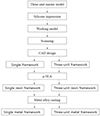
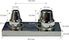
For this study, the followings were used to create a threeunit master die. The two abutments started out as a wax block (Vipi Block Wax, Vipi, Pirassununga, Brazil) that was used only for milling, whereas the center section of the abutment was designed for making the pontic.9 The angles of the axial walls were 6°, and the abutment was prepared using a 360° chamfer. After that, the three-unit master model was finished by casting it with metal alloy (Fig. 1 and Fig. 2).
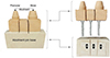
In order to make a working die from the prepared master one, 10 silicone impressions (Aquasil Ultra XLV and Ultra Rigid, DENTSPLY DeTrey GmbH, Konstanz, Germany) were prepared and used to develop 10 scannable die stones (Esthetic-base gold, Dentona AG, Dortmund, Germany). A mixing machine was used to mix 100 g of powder and 20 mL of liquid for 60 seconds. Pins were used to separate the bases of the molar/premolar abutments and the pontic base (Fig. 3).
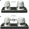
The prepared stones were scanned with a model scanner (Identica Blue, Medit, Seoul, Korea) whose data were transferred and saved as an STL (stereolithography) file. This was processed with CAD software to design the molar/premolar single frameworks, which were 0.5 mm thick. A 50 µm space was left between the axial wall and the occlusal gap, but no marginal gap was included. A non-pontic was also designed for between the abutments. The scan data were used to set the molar/premolar three-unit frameworks, which were 0.5 mm thick.1013 Again, the axial-wall/occlusalgap space was 50 µm with no marginal gap, but now a pontic was designed to be between the abutments.20 Each CADprocessed STL file was sent to the µ-SLA inventory and the SM/TUM resin frameworks were printed.
Each framework group was invested (Formula1, Whip Mix Corp., Louisville, KY, USA) in accordance with the manufacturer's recommendations as follows. A combination of 22 mL of liquid and 100 g of powder was mixed by hand for 10 seconds and then by a mixing machine for 120 seconds. The resin was melted at 925℃ for 2.5 hours. The alloys were cast centrifugally to create the metal frameworks (Fig. 4).2122
1/4 of light-body silicone was injected into the two prepared metal frameworks at a pressure of 50 N for 10 minutes.23 The metal framework was then carefully separated from the light body so that the latter was not damaged. A prepared baseplate wax (Hard wax, Daedong in., Daegu, Korea) was used on the light body to make a rectangular tray and inserted the medium body to it. Inside this, a film was wrapped on the master die and the light body. The distal surface of the cured silicone replica was cut carefully. The sliced part of the light-body silicone area was measured under a digital microscope (HK-7700, HIROX, Tokyo, Japan)(Fig. 5).2
A statistical software (IBM SPSS Statistics for Windows, V22.0; IBM Corp., Armonk, NY, USA) was used to show that the metal framework's measurement data reached 95% of normality; however, they did not reach an acceptable normality. They also did not perform satisfactorily for Levene's variance homogeneity test. Therefore, the Mann–Whitney U test was used instead, which is a non-parametric validation process (α = .05).
RESULTS
Table 1 lists the mean and standard deviation for each of the gap widths that were measured in this study. It is clear that the mean values for the SM group of samples are less in each case than those for the TUM group. However, there was no statistically significant overall difference between the two groups. The axial wall gap did show a significant difference (P < .05), whereas the chamfer and occlusal gaps did not (P > .05). The widest gap was found to be the occlusal one for both groups, but again with no significant difference (P > .05).
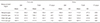
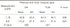
Table 2 lists the gap-width means and standard deviations in terms of the premolar and molar groupings. In the premolar case, the marginal and chamfer gaps appeared to be narrower and more consistent in the TUM group than in the SM one. However, the difference proved not to be statistically significant (P > .05). In the molar case, the SM gap widths were more consistent than those of the TUM group, but the differences in the mean values were again not statistically significant (P > .05).
Table 3 lists the marginal-gap data in terms of the pontic and non-pontic areas. The TUM group had the narrower gaps at measurement points 1 and 16, whereas the SM group had the narrower ones at points 8 and 9. The SM group showed no statistically significant difference between points 1 and 16 and points 8 and 9, whereas there was such a difference in the TUM group.
DISCUSSION
The aim of this study was to analyze the marginal and internal gaps in both SM and TUM frameworks. Each metal framework was created by the sequence of forming the shape, scanning, CAD processing, resin-framework fabrication, investment, burnout, and casting. During the CAD stage, no occlusal cement gap was included, whereas an internal gap of 50 µm was specified. The molar and premolar thickness was set as 0.5 mm. After creating the metal frameworks, the silicone replica technique was used, from which the marginal and internal gaps were measured under a microscope.
In terms of a comparison between the SM and TUM groups (Table 1), the marginal gap was narrowest on average for the SM one. However, both groups were proved to be acceptable for clinical purposes, given that their marginal gaps were < 120 µm with no statistically significant difference. The axial wall gap was relatively small in both groups, and the widest gap was consistently the occlusal one. Despite being relatively small, the axial wall gap showed a statistically significant difference between the two groups. This was considered to be a consequence of metal shrinkage caused by the pontic on the axial wall,21 given that this feature was the significant difference between the SM and TUM groups.
In terms of a comparison between molar and premolar data (Table 2), there were again statistically significant differences in the axial wall gaps of the two groups. The TUM group, which has a connection area, had the wider axial gaps in both cases at statistically significant levels.
In terms of a comparison between pontic and non-pontic designs (Table 3), the marginal gap at measurement points 1 and 16 was narrower in the TUM group than in the SM one at a statistically significant level. However, the same gap at points 8 and 9 was narrower in the SM group, again at a statistically significant level. We consider these results to be a consequence of metal and resin shrinkage at points 8 and 9 caused by the connector and the pontic. Moreover, the TUM differences were far more statistically significant. This was again attributed to the fact that the existence of a pontic means that the TUM group is affected by contraction. A marginal gap of 143.7 µm at measurement points 8 and 9 suggests that the TUM group requires more investigations before it can be applied clinically.
The research showed that both TUM and SM groups resulted in large means and standard deviations. Such phenomena most likely occurred because µ-SLA relies on UV light sources. When UV light passes through the liquid polymer, some of the light is lost because of diffraction.16 Also, it is possible that human error enters at the investment, burnout, and casting stages.8 With further research into the µ-SLA method used for this study, the cost of creating a metal framework can potentially decrease. With this potential advantage, this particular method could be used to create the next mainstream restoration in the field of dentistry.
There were limitations to this research. The TUM master die used to create the abutments did not have the precise shape of an actual tooth. Therefore, its clinical use is necessarily limited. Our study used Ni-Cr alloy to make the metal framework. Although this alloy is still currently being used, Co-Cr one is becoming increasingly popular. Hence, in order to conduct proper and precise research, a practical abutment and Ni-Cr alloy should be used to test the results, while research into the three-unit resin framework should also be carried out.
CONCLUSION
Single metal frameworks showed a more acceptable fit than did three-unit ones. Moreover, the three-unit metal framework had an overall marginal gap that appeared to be suitable for clinical purposes. However, when viewed in more detail, the pontic areas showed marginal gaps that would not be acceptable clinically.

 XML Download