

 PDF
PDF ePub
ePub Citation
 Print
Print


INTRODUCTION
Technology is advancing day by day. In dentistry, different impression techniques are also evolving. Optical cameras have been developed to create impressions for prosthodontics, implantology, or orthodontics.12 Besides the time saved and improved communication, these also seem to offer greater precision.3 Equipped dentists are now using 3rd generation optical cameras, yet conventional impression techniques are still being employed. The materials required for the latter technique have not followed the vast and rapid evolution of the optical cameras.4 Though still a little-known technique from just a few years ago, optical impression has quickly evolved and offers solutions for larger volume registration in different domains (prosthetics, implantology, orthodontics).2
Optical impression has the advantage of being fast, reducing procedure time, and requiring less data storage compared to the space needed to store models. CAD/CAM systems are classified as closed or open systems. This classification is based on data sharing.1 Closed CAD/CAM systems involve that the data acquisition, virtual design, and restoration manufacturing have to be done by the same company, which has the disadvantage of forbidding interchangeability between systems from other companies. Open systems allow acquisition of the digital data by CAD software and CAM devices from other companies.1
After image acquisition, the information is sent to a laboratory scanner or to a outsource production center. Optical impression is especially indicated for prosthodontics. However, the use of optical impression is less involved in the realization of overdentures because of its lack of efficiency to read gingival surfaces. Also, for fixed prostheses, the cervical margin is a zone of paramount importance to dental restoration success. As for the subgingival margin, only conventional impression is currently capable of registering it.5
Conventional impression has the advantages to be be adapted for every situation (supra- or sub-gingival margins, complete edentulous), therefore needing less investments and occupying less surface than CAD/CAM systems.12
The aim of this study is to assess whether the marginal adaptation of a restoration based on optical impression is better than that based on conventional impression. We also aim to compare three types of cervical margin (shoulder, chamfer, knife-edge) and observe if there is a difference between their marginal adaptations.
To this end, we conducted an in vitro experimental study in order to compare the adaptation of zirconia crowns on Frasaco teeth following an impression achieved in one or the other impression techniques and also to compare three different finish lines (shoulder, chamfer, knife-edge). Unfortunatly, there is currently no standardized method to evaluate the adaptation of dental restorations.3
MATERIALS AND METHODS
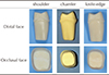
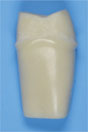
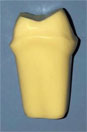
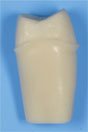
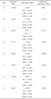
Three different crown preparations were conducted on a Frasaco model left maxillary first molar (Frasaco GmbH, Tettnang, Germany; Table 1), with three different finishing line preparation:
The criteria of the three designs were: 6° convergence and 1 mm marginal limit.
For each preparation, two types of impression were conducted: one conventional, one optical.
The conventional impression (double-mix) of the upper maxillary was performed using Imprint IV with a silicone A (3M-ESPE, St Paul, MN, USA).
Heavy Body was injected into a green impression tray (REF 150-204-00, Dentaurum, Inspringen, Germany) using a Pentamix (3M-ESPE), then Light Body was injected around the preparation and adjacent teeth. An impression of the antagonist was then created using alginate (NORMAL SET, Cavex Impressional, Haarlem, The Netherlands).
The models were created with Selexion fast-setting plaster IV (REF 959223, Arseus Lab., Colmar, France), and placed on the stand. Before scanning the models, preparation occurred manually. The die was separated from the rest of the model, and the prosthetist then used this die to mark out the preparation's limit using a tungsten carbide bur (REF H263SH60, Bredent, bredent GmbH & Co.KG, Senden, Germany).
Next, the die was placed on the model and scanned (3Shape 15.6.1 software, Copenhagen K, Denmark) in three parts:
The resulting scan was then converted to STL format (Standard Tessellation Language).
Optical impression of the upper model, of the antagonist, and of the models in occlusion were performed using the 3Shape Trios optical camera.
The resulting STL files were sent directly to the prosthetics laboratory.
The CAD/CAM technology was used to achieve digital impression. This signifies the computer-aided design and manufacture (CAD/CAM) process of creating zirconia crown, using 3Shape software.
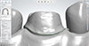
The parameters (interfaces and framework design) were those set by 3Shape, notably with a 45-µm spacer (Fig. 1). The Ceramic Match2 program (Amann Girrbach, Koblach, Austria) and the Motion 2 software (milling machine) were used for creating the crown.
The 60 zirconia crowns created were baked for 12 hours at 1300℃ in an oven. Finally, the extrados edges were polished. It should be noted that the intrados was not readjusted in any way.
A C silicone putty index (Hard 85 shore A, Zetalabor Zhermarck, Wittelsheim, France) was made with an edge corresponding to the mark on the Frasaco tooth in order to cut each 20 crowns down the middle in exactly the same place, using a diamond cutting disc (REF 34000520, Bredent) set at 10,000 to 15,000 rpm.
The tooth was then cut along the palatine-vestibular plane. The distal part was conserved for SEM (scanning electron microscopy) analysis, for each half crown.
The 60 zirconia half-crowns were divided into six groups according to the type of impression (conventional versus optical) and margin (shoulder, fillet or chamfer) and each half-crown was analyzed by SEM.
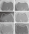
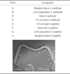
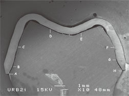
Another silicone index (Fit checker, GC, IL, USA) was then created in order to fix the half-crown onto the Frasaco half-tooth. No cement- or glue-type substances were used to fix the crown on the tooth. The tooth and crown intrados were coated by gold plasma in order to render the samples visible on SEM (JSM-6400, Jeol), applying ×10 enlargement (Fig. 2).
Using image editing and analysis software (ImageJ), the gap between the preparation and zirconia crown was measured at eight reproducible and standardized points in order to compare adaptation between the conventional impression and optical impression groups, as well as that between the different margin types (Table 2, Fig. 2). All measurements were taken by the same investigator.
Other gaps besides those at these eight points were not, however, registered.
The results of the different measure points were statistically analyzed using the IBM SPSS Statistics Version 23 program. Two-way analysis of variance (ANOVA) was used for the statistical analysis of each measuring point. Two particular elements could thus be compared: first the inter-subject influence of the “impression” factor (conventional versus optical), and second, the inter-subject influence of the “margin type” factor (shoulder, chamfer, knife-edge), as well as impression-margin interactions.
RESULTS
The only statistically significant effect of the impression technique was observed for A points (vestibular marginal gap) and B (edge of the vestibular preparation). The zirconia crowns created using optical impression demonstrated better marginal adaptation at the vestibular edge (point A) (average = 59.10 ± 29.94 µm) than that created using the conventional impression (average = 79.27 ± 31.91 µm). For the other six points (C to H), no statistically significant differences (P ≥ .05) were observed between the two impression types: conventional versus optical (Table 3).
Contrary to the effect of the impression, different results were obtained with the various margin types. Each of the eight measure points demonstrated at least one statistically significant difference (P < .05), and for six (A, B, D, E, F, H), the difference was highly significant (P < .001) between the margin types. For point A (vestibular marginal gap), a highly significant difference was noted between the edge produced using a chamfer shape (more precise) and that using a knife-edge. A significant difference was noticeable between the shoulder (more precise) and chamfer shapes. Points B (vestibular edge of the preparation) and H (palatine marginal gap) exhibited extremely significant differences for all shapes. The results of point C (vestibular axial wall) indicated just a slightly significant difference between the chamfer and knife-edge shapes. For points D (vestibular occlusion third) and E (palatine occlusion third), an extremely significant difference was observed between the shoulder and chamfer shapes, as well as between the chamfer and knife-edge. A significant difference was also observed between the shoulder and knife-edge shapes for point D. The measurements for point F (palatine axial wall) revealed highly significant differences between the chamfer and knife-edge shapes and shoulder and knife-edge shapes, and extremely significant difference between the shoulder and chamfer shapes. The results of point G (palatine preparation edge) indicated a statistically significant difference between the shoulder and knife-edge and highly significant difference between the shoulder and chamfer. In other words, the shoulder and chamfer shapes produced statistically significant differences across all measuring points, except that of the axial vestibular wall (point C), all in favor of the chamfer margin type. Comparing the chamfer and knife-edge shapes, at least one statistically significant difference was observed for seven of the eight points. In terms of all the differences, the shoulder shape appeared to present the least statistical differences as compared to the knife-edge shape, namely in five of the eight points.
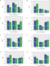
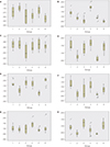
Table 4 presents the average gap values and standard deviations of the recorded values for the six groups (points A to H). Only points A (vestibular marginal gap), C (vestibular axial wall), and F (palatine axial wall) presented values all under 120 µm.3 Fig. 3 and Fig. 4 display our results.
On statistical analysis, the impression-margin type interaction revealed only one highly statistically significant difference (P < .001) for point B and one significant statistical difference (.01 ≤ P < .05) for point C. This indicates that the difference between these two impression types is nearly independent of the margin design used for each measurement point.
DISCUSSION
The first optical camera appeared in 1987 with the 1st generation Cerec. After some modifications and improvements, it was more widely used in the early 2000s and new brands appeared, including for example, the 3M ESPE (Lava COS système), 3Shape (Trios), and Cadent (iTero).6
Optical impression is faster than conventional impression.7 This time-saving is particularly valuable in cases where a missed or misregistered zone requires re-registration. In conventional impression, such an error can require an entire new impression. Using the optical camera has also been shown to afford better acceptance of the treatment plan and improved comfort for the patients (gag reflex, limited mouth opening, for example). The potential errors in conventional impression can occur in distortion, material damage (retraction of the impression, temperature fluctuations, transport) when casting the impression, faulty articulator set up, and the laboratory procedures.
Our results demonstrate there is no significant difference between the two impression types (conventional and optical), except for points A and B. The choice of impression type thus does not influence the precision of the zirconia crown's adaptation. This is in line with previously published results.891011
Nevertheless, other studies have underlined the superiority of adaptation of crowns created using optical impressions compared to those using conventional impressions.7121314151617 As an indirect CAD/CAM technique, conventional impressions are transmitted to a prosthetist who then conducts the digital acquisition of the data, by scanning either the impression or the model itself. This additional step can lead to inaccuracies.
Few articles have argued the contrary.18 The steps required for silicone impression and casting the plaster can, in fact, induce deformities, creating the risk of errors that thus reduce the possibility of achieving the best crown adaptation based on conventional impression.19
It is particularly challenging to compare our study with previously published ones, as the methods and protocols vary. Less focus has previously been given to the materials used in conventional impression, and even less to the techniques used.
In dental restorations with fixed prostheses, the margin type appears to be the most technically challenging element. The finishing margin line must take into account tissue saving, preserving good gingival health, overall esthetic (gingival smile, contours...), and the emergence profile, as well as the restoration material. Yet the choice of materials for restoration is rarely taken into account, despite the adaptation and fracture risk (dependent on stress distribution) being strongly impacted by this factor. We thus opted to use zirconia in our study as it is strong, rigid, and remains stable in high temperatures (more so than metals).20
When measuring chewing-related constraints, irrespective of which material was chosen, the highest values were particularly those measured at the cervical line of the restorations.21 Some authors have suggested that shoulder-margin preparations offer better resistance to fracture along with improved biomechanical efficiency.22 Other studies have claimed the chamfer shape offer better resistance to fracture than the shoulder or knife-edge designs. These authors judged that zirconia preparations, not using the shoulder shape, have a better stress distribution in the material.232425 In our study, there was a significant difference between the three margin types: the chamfer and knife-edge finishing lines appeared to offer better adaptation results than the shoulder. This could be due to the optical camera having difficulty reading clear 90° angles.21 In fact, Jalalian et al.21 reported that the chamfer edge's curved shape with a round internal angle causes a neater finishing line for the restoration. Similarly, stress is better distributed in the structure as a result of this. With 90° angles, though, the configuration is different; the marginal finish is thicker, the piece is adhered to the dental structure, and the volume of the restoration-glue-surface structure is greater. This leads to higher fracture rates caused by the presence of an internal marginal angle, as opposed to the angles in the chamfer design.2122232425 On the other hand, Mitov et al.26 reported less fractures with shoulder preparations. However, this type of preparation is not recommended due to harmful periodontal considerations.
Nevertheless, only few articles have compared the three types of margin finish lines as we have done. One study by Komine et al.27 demonstrated no significant difference among the three. The others compared two types, reporting no difference between the knife-edge and shoulder shapes or chamfer and shoulder shapes,28 or between the knife-edge and chamfer designs.29
One study2 employed micro-computed topography (CT) to evaluate the adjustment of dental restorations created using optical impression (LAVA, 3M-ESPE), demonstrating that the CAD/CAM technique did not succeed in creating a homogenous and identical space between the preparation and crown, despite using a 20-µm uniform spacer. The same conclusion was drawn from our findings, despite using a similar 45-µm spacer.
It should be noted that several studies are in agreement that a marginal space inferior to 120 µm is acceptable.2
Comparing the averaged gap values in µm, our study recorded averages inferior to 120 µm for the chamfer finishing lines, considering both types of impression and all eight measure points. Our results confirmed that a chamfer finishing line enables acceptable adaptation of zirconia crowns.
Of all the averaged values of the gaps between the Frasaco teeth and zirconia crowns, 25% were over the acceptable value of 120 µm. Points D and E, corresponding to the occlusion, presented values superior to 120 µm, both with shoulder and knife-edge shape designs, in both the conventional and optical impression groups. This adaptation difference is notably in line with that reported in another study3, in which a significant difference was reported between the different point measurement values. We also observed that the marginal space in our study was inferior to that of the occlusion.
CONCLUSION
Within the confines of our study, we demonstrated that the type of margin used is significant in terms of the marginal adaptation of the zirconia crown. Therefore, shoulder-margin preparations should preferably be avoided, for both periodontal and biomechanical reasons. Chamfer preparations should be favored, offering a curve and round internal angle that ensures a neater restoration finishing. That being said, the choice of impression technique was not found to influence the resulting adaptation of the zirconia crown. While providing similar results, the optical impression technique does, however, offer many advantages over the conventional option. Therefore, digital technology is likely to become more prevalent in daily practice.

 XML Download