

 PDF
PDF ePub
ePub Citation
 Print
Print


INTRODUCTION
The lost-wax technique, introduced by Taggart in 1907, enabled the manufacturing of various fixed restorations in the dental industry.123 Manufacturing restorations with the lost-wax technique involves manual wax carving, investment, burn-out, and casting with metal ingots to make a fixed restoration. However, this method is time-intensive and yields inconsistent results.
Recently, computer-aided design/manufacturing (CAD/CAM) systems with the potential to overcome the shortcomings of the lost-wax technique are being introduced.456 Dental CAD/CAM systems can be divided into 2 categories as follows: subtractive manufacturing that mills from a solid block and additive manufacturing that layers materials.7 The subtractive manufacturing method uses milling tools to handle any material and provides high accuracy and sophisticated surfaces. However, complicated casts are difficult to mill, and studies have reported that errors may occur due to milling bur erosion during the milling process.89 Furthermore, the waste materials after milling cannot be reused, making subtractive manufacturing material costs high. Additive manufacturing is emerging as a potential solution to the problems of subtractive manufacturing. Additive manufacturing enables the creation of sophisticated casts and reduces manufacturing material costs.10
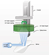
Microstereolithography (µ-SLA), a dental additive manufacturing based on the CAD/CAM system, is a photo-hardening technique similar to the existing digital light processing (DLP) technique that enables the manufacturing of various resin copings. An ultraviolet (UV) light source shines on a mirror, and the reflected light casts an image on the UV-curable liquid resin, which is then layered into the desired shape.11 The use of micro-level resolutions enables this method to accurately generate even complicated threedimensional (3-D) images.12
By using this system, the dental industry has been able to easily manufacture lower structures of porcelain fused to metal (PFM). Most lower structures were manufactured with common metal alloys. Nickel-chromium (Ni-Cr) or cobalt-chromium (Co-Cr) alloy copings were usually manufactured.31314 The lower structures of metal copings were made from Ni-Cr alloy. However, as beryllium is a known carcinogenic substance and as many individuals have allergic reactions to Ni, reports of the negative effects of copings on human biology have increased.151617 To address these problems, recent clinical studies have introduced the more biologically friendly Co-Cr alloy copings to the field of research.
The most important characteristic of µ-SLA-manufactured metal copings is the marginal fit. If the marginal fit of the restoration is not superior, marginal leaks may occur, which lead to plaque retention and alteration of the distribution of the microflora.18192021 As a result, hypersensitivity and secondary caries may occur, which can lead to restoration failure.20 Hence, various ranges of fit have been proposed. In general, the range proposed for clinical application is within 120 µm.22232425262728
Therefore, the purpose of this study was to evaluate and compare the marginal and internal fit of dental µ-SLA-manufactured Ni-Cr and Co-Cr alloy copings. The null hypothesis was that no difference would be found between Ni-Cr and Co-Cr alloy metal copings fabricated using the micro-stereolithography system.
MATERIALS AND METHODS
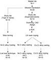
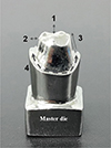
The master die in the present study was selected to be the mandibular right first molar (ANA-4; Frasaco GmbH, Tettnang, Germany) (Fig. 1). The selected acrylic molar was then cut into an abutment tooth for a metal-ceramic crown. Around 2 mm of the occlusal surface and 1.5 - 2 mm of the axial surface were prepared, and the axial wall was milled into a 6° taper, with a 360° chamfer margin. The abutment tooth was then replicated with silicone (Deguform; Degudent GmbH, Hanau-Wolfgang, Germany). Wax (Geo Wax, Renfert GmbH, Hilzingen, Germany) was poured into the replicated silicone to obtain a wax master die. This die was cast into a metal master die (Fig. 2).
A two-step silicone-impression technique with silicone impression materials (Aquasil Ultra XLV and Aquasil Ultra Rigid, Dentsply DeTrey GmbH, Konstanz, Germany) was applied on the master die to produce 20 silicone impressions. Among the 20 impressions, 10 were poured with type IV stone (GC Fujirock EP, GC Corp, Leuven, Belgium) to produce 10 type IV stone study dies. The other 10 were poured with a scannable stone (Esthetic-base gold, Dentona AG, Dortmund, Germany) to make 10 scannable study dies.
The 10 wax copings were manufactured using the lost-wax technique as follows: the cement space of the prepared study die of type IV stone was made using a die spacer (Nice Fit, Shofu Inc., Kyoto, Japan). The covering method is described below. Three coverings were coated, each cover having a thickness of 10 µm, for a total of 30 µm. Ten wax copings (GEO, Renfert GmbH) for the PFM were manufactured by hand. While carving, the wax coping thicknesses were regulated to 0.5 mm on the buccal, lingual, mesial, digital, and occlusal surfaces with a wax device (C220, Kroeplin, Schluechtern, Germany).
The 10 prepared scannable study dies were scanned with a cast scanner (Identica Blue, Medit, Seoul, Korea). The finished stereolithography (STL) files were input with a cement space of 30 µm and a thickness of 0.5 mm with CAD software (Exocad DentalCAD, Exocad GmbH, Darmstadt, Germany). The copings were manufactured with these 10 finished STL files. The finished STL files were applied to the µ-SLA (Projet 1200, 3Dsystems, Rock Hill, SC, USA) to make 10 resin copings for the NC group and 10 resin copings for the CC group, for a total of 20 resin copings (VisiJet FTX Green, 3Dsystems, Rock Hill, NC, USA) (Fig. 3). During this process, the copings underwent post-curing with the UV lamp of the µ-SLA. Then, after the resin supports were detached, the surfaces were smoothened.
Ten wax copings manufactured with the lost-wax technique and 20 resin copings manufactured with the µ-SLA system were invested according to the manufacturer-recommended liquid/powder ratio of 22 mL/100 g (Formula1, Whip Mix Corp., Louisville, KY, USA). They then underwent burnout at 925℃ in a furnace for 2 hours 30 minutes. The LW and NC groups were cast using Ni-Cr alloy (VeraBond 2V, Aalba Dent, Fairfield, CA, USA), whereas the CC group was cast using Co-Cr alloy (StarLoy C, DeguDent, Hanau-Wolfgang, Germany) (Table 1). A gas-oxygen torch was used to melt metal ingots into a broken-arm centrifugal casting machine for the casting process.2930
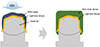
The silicone replica technique was used in this study to evaluate the marginal and internal fit of Ni-Cr and Co-Cr copings, as seen in Fig. 4.3132 The interior of the metal coping was filled with light-body silicone (Aquasil Ultra XLV, Dentsply DeTrey GmbH), and after attaching the coping to the master die, 50 N of pressure was applied using a press machine (Instron 3345, Canton, MA, USA). The pressure was maintained for 5 minutes until the light-body silicone hardened. After hardening, the coping was carefully released, and heavy-body silicone (Aquasil Ultra Rigid, Dentsply Detrey GmbH) was added to the light-body silicone film to stabilize the structure. The silicone replica was cut in the buccal/lingual and mesial/distal directions, and 16 areas were selected to be measured with a 160× digital microscope (HK-7700, HIROX, Tokyo, Japan) (Fig. 5).
A normality test was conducted, but the data were not normally distributed. Therefore, a non-parametric Kruskal−Wallis H test was conducted, and each group was evaluated with a post-verification Mann-Whitney U test with Bonferroni correction. The significance level was set to 0.05. The used software was IBM SPSS (IBM SPSS 22.0, IBM Corp., Armonk, NY, USA).
RESULTS
Table 2 shows the mean ± standard deviation of marginal and internal gaps in the LW, NC, and CC groups. The NC group showed the lowest average gap of 76.8 ± 48.0 µm, whereas the CC group showed the highest average gap of 124.2 ± 52.0 µm. In terms of standard deviation, the NC group had the lowest deviation, whereas the LW group had the highest deviation. All the groups showed statistically significant differences in marginal gap value (P < .001).
In the chamfer area, all the groups showed statistically significant differences in gap values (P < .001); the LW group showed the lowest gap (98.1 ± 76.1 µm) and the CC group showed the highest gap (199.51 ± 71.0 µm).
In the axial wall area, the CC group showed the lowest gap (67.1 ± 37.6 µm), which was statistically significantly different from the LW group (87.1 ± 44.8 µm) (P = .031). In the occlusal area, the LW group had the lowest gap (146.8 ± 78.7 µm), whereas the CC group had the highest gap (244.5 ± 58.9 µm), with statistically significant differences (P < .001).
DISCUSSION
Previous reports have indicated that the conventional lost-wax technique is time-costly, due to the complicated manual works involved, and that distortion occurs while removing the finished wax patterns.6 These problems were resolved using the recently introduced automatic µ-SLA system. In this study, resin copings were manufactured using the µ-SLA system and were then cast to produce Ni-Cr and Co-Cr alloy copings. Fit was evaluated and categorized into the following 4 areas: marginal, chamfer, axial wall, and occlusal gaps. Each gap was measured and evaluated.
Previous reports have recommended various methods for evaluating fit. In marginal fit research, the most common method used is cementing or the silicone replica technique.31 Cementing involves pressing cement material with the restoration onto a prepared abutment tooth. The abutment tooth and the restoration are cut, and the cement thickness of the cross-section is measured.32 This method has the major disadvantage of destroying both the restoration and abutment tooth, yielding only 1 measurement per object. However, the silicone replica technique uses light- and heavy-body silicone materials and measures the thickness of the light body, enabling various cross-sectional measurements. As the restoration remains intact, repeated measurements can be performed. Hence, this study selected the silicone replica technique to measure marginal and internal fit.
The clinically accepted ranges of marginal fit reported in the literature differ. Some researchers argues that < 50 µm is a superior value, but most researchers have used values of < 100 - 150 µm as the range of clinically acceptable marginal fit.22232425262728 However, due to the rapid advancement of automatic systems, the range of marginal fit has now been set to < 120 µm.
In this study, the groups that satisfied the marginal fit limit was the LW-manufactured Ni-Cr alloy group, with a gap of 81.5 ± 73.8 µm, and the NC group, with a gap of 76.8 ± 48.0 µm. In these 2 groups, the most superior marginal fit was that of the µ-SLA-manufactured Ni-Cr coping NC group. Given the risk factors of manual works, the LW group had higher mean and standard deviation than the NC group.6
On the other hand, the NC and CC groups were uniformly manufactured by means of an automatic system. As they were not exposed to any risk factors, the error margins of the copings were small. The CC group, manufactured with biologically friendly Co-Cr alloy materials, had the highest marginal gap value. In terms of internal fit, the lowest gap value was observed in the axial wall and the largest value in the occlusal. This is because the compatibility between the Co-Cr alloy and the investment material is worse than that of the Ni-Cr alloy and the investment material.3334
The occlusal gaps were higher in the NC and CC groups than in the LW group. According to previous studies, the reason for this large gap in the occlusal area is a common phenomenon observed in dental CAD/CAM systems.28 Furthermore, this study shows that the small gap in the axial wall area may also greatly affect the marginal gap. The reason for the relatively high standard deviation values for all 3 groups arose from reducing errors while investing and casting the metal copings.2930 In addition, because µ-SLA systems use light to manufacture copings, diffraction is seen to be a factor in lowering accuracy and raising deviation.
The main limitation of this study is that the Ni-Cr and Co-Cr alloys were procured from only one manufacturer and thus may be inappropriate for generalization. In addition, this was an in vitro study and measured the fit without considering the actual intraoral environment. Moreover, clinical usage was evaluated without using the actual cement material used in restorations.
This study highlights the need for clinical evaluations that use various commercial Co-Cr alloys with the µ-SLA. In future studies, marginal fit evaluations should be extended from a single coping to a long or partially fixed dental prostheses and a built-up PFM. Furthermore, optimal fit studies should be performed using Co-Cr alloys and appropriate investment materials.
CONCLUSION
The difference in fit between the Ni-Cr and Co-Cr alloy types was significant. The group that showed the best fit was the µ-SLA-manufactured Ni-Cr coping in the NC group, with a clinically acceptable marginal gap. However, Co-Cr copings require more research before they can be applied in clinical practice.


 XML Download