

 PDF
PDF ePub
ePub Citation
 Print
Print


INTRODUCTION
Dental prostheses can replace lost or damaged teeth. Thus, they should be manufactured using aesthetically acceptable, durable, precise, and biocompatible dental materials in order to replicate the function of natural teeth as closely as possible.1
Dental ceramic has well-established efficacy in its use as the material for dental prostheses.2 It was developed to satisfy the aesthetic expectations of patients and has been widely applied.3 Zirconium dioxide (zirconia) ceramic material is comparable in color with natural teeth and has a flexural strength of 900 - 1200 MPa, which is comparable with that of metal.4 Lithium disilicate ceramic material has better transparency than zirconia.5 In addition, it has excellent properties such as biocompatibility, chemical stability, and mechanical strength.6 Furthermore, veneers, inlays, prostheses in the form of crowns, and three-unit anterior fixed partial dentures have been utilized as dental prostheses.7 Lithium disilicate ceramic materials produced by the computer-aided design/manufacturing (CAD/CAM) technique and zirconium dioxide ceramic materials have volume shrinkage rates of 0.25% and 22 - 25%, respectively, during sintering.8910 Therefore, these two materials may negatively affect the fit of a dental prosthesis owing to shrinkage in pre-sintered blanks during the sintering process.7 In contrast to ceramics, Polyetherketoneketone (PEKK), a new material in the dental field, does not exhibit shrinkage. Furthermore, PEKK exhibits highly biocompatible characteristics that are desirable in the medical industry. For these reasons, PEKK has been utilized as the primary transplantation material, adequately replacing titanium, a material that was used for a considerable length of time in orthopedic applications.11121314
Fuhrmann et al.11 reported that PEKK can provide a solid production in the manufacturing of crowns and fixed dental prostheses (FDPs). In particular, crystalline PEKK is utilized for crowns and FDPs, while amorphous PEKK is used for removable prostheses. Crystalline PEKK and amorphous PEKK are resistant to chemical wear, have high mechanical resistance and tensile and flexural strengths, can withstand high temperatures (melt temperature, 300℃) and have high-quality characteristics of good dimension stability.1115 In addition, according to Stawarczyk et al.,16 PEKK is biocompatible, and in contrast to metal restorations, it has an appearance similar to that of natural teeth. It can also be easily formed with a simple dental bur. However, considering its aesthetic qualities, PEKK has low transparency and a grayish pigmentation when compared with natural teeth (or dental ceramics), and cannot be processed in an overall shape.16 Therefore, it is predominantly manufactured within a framework.
The complexity associated with the manufacture of dental prostheses has led to the development of the CAD/CAM technology that can eliminate errors in temporary elements during the traditional manufacturing process of dental prostheses.17 CAD/CAM not only is efficient, but also has standardized repeated accuracy.2 Furthermore, CAD/CAM systems have revolutionized manufacturing processes in the dental industry, enabling the rapid production of simple prostheses.18 In a study by Rudolph et al.,17 the utilization of oral scanners was found to eliminate the error incurred during the operative course of the impression and plaster model. A CAD/CAM system with an oral scanner has also been reported to be associated with valid and prompt manufacturing.2
The accuracy of the milling process is largely affected by the axis of the milling machine, and the current milling machines are distributed as 3-, 4-, and 5-axis milling machines.19 While 3-axis milling has a short production time and simple operation, there is a limit in milling the inner surface of the tooth restoration, which is a free-form curved surface as there is no rotating shaft.19 Therefore, a 4-axis milling machine with three axis added to the rotation axis and a 5-axis milling machine with two rotation axes were developed.19
According to Bosch et al.,2 the 5-axis milling machine has better accuracy than a 4-axis milling machine. However, using a 4-axis milling machine is cheaper than using a 5-axis milling machine, reducing the cost of the prosthesis.20 In addition, the digital simulated process has been reported to reduce the process time and manufacturing waste; thus, 4-axis milling is a practical method for creating free-form surfaces.20 The number of the milling axis is not necessarily proportional to the level of accuracy, but it has a wider impact on accuracy digitization, data processing, and production processes.
The accurate manufacturing of dental prostheses is important for long-term clinical applications.21 Accuracy and precision between abutment teeth and dental prostheses are required in the manufacturing process of dental prosthesis. Inaccurately manufactured dental prostheses can lead to secondary caries, marginal microleakage, periodontal inflammation, periodontal lesion, plaque accumulation, and nonsurgical endodontic treatment.72122 Therefore, manufacturing dental prostheses with an accurate margin is important. The silicone replica technique (SRT) has been frequently utilized owing to its ability to measure the fitness of a dental prosthesis without causing damage.2324 However, numerous studies have failed to validate the accuracy of measurements using the SRT. Studies investigating the accuracy of two-dimensional (2-D) sections of three-dimensional (3-D) superimposition analysis (3DSA) are relatively rare. Therefore, the purposes of this study were to (1) evaluate the marginal and internal gaps in three types of dental prostheses (subtractive manufacturing systems using a lithium disilicate crown [LC], zirconia crown [ZC], or PEKK crown [PC]) and (2) to compare between the measurements obtained from using the SRT (control group) and those obtained from using the 2-D sections of the 3DSA method (test group). The null hypothesis tested was that the marginal and internal gaps do not significantly differ among the three groups or between the two measurement methods.
MATERIALS AND METHODS
An acrylic model (AG-3 ZPVK 16 [maxillary right first molar]; Frasaco GmbH, Tettnang, Germany) with abutment teeth was used. Therefore, the maxillary right first molars were prepared with a 360° 1.0-mm deep chamfer. The occlusal reductions ranged from 1.5 - 2.0 mm.25 The master model was created with silicone (Deguform, DeguDent GmbH, Hanau, Germany) by pouring polymethyl methacrylate (PMMA; JT, Lang Dental Mfg. Co. Inc., Wheeling, IL, USA),26 which has a reflective index within the range of a natural tooth, into the maxillary buccal flange of the replicated silicone.
A RST-CEREC file was obtained using Omnicam (CEREC Omnicam, Sirona Dental System GmbH, Bensheim, Germany) with the master model. According to the manufacturer's instructions, we designed the clinical crown with CEREC inLab software (Sirona Dental System GmbH) with the RST-CEREC file. Before the crowns were designed, the following design parameters were set: spacer value, 30 µm; occlusal thickness, 1.5 mm; and axial thickness, 0.8 mm. With the designed file, each pre-sintered LC (IPS e.max CAD, Ivoclar Vivadent AG, Schaan, Liechtenstein) and presintered ZC (Sirona inCoris TZI, Sirona Dental Systems GmbH) was milled five times, under one file, with a fouraxial milling machine (inLab MC XL, Sirona Dental System GmbH).2 The IPS object refill putty pin was fixed to the inner surface of the pre-sintered LC. Five LCs were produced based on the sintering manual provided by the manufacturer with a dental ceramic furnace (Programat P310, Ivoclar Vivadent). Five ZCs were created with a specific furnace (Sirona inFire HTC, Sirona Dental Systems GmbH) based on the sintering manual provided by the manufacturer.
The master model was replicated with light-body silicone (Aquasil Ultra XLV Regular Set, Dentsply Caulk, Milford, DE) and heavy-body silicone (Aquasil Ultra Rigid Regular Set, Dentsply Caulk) to obtain an impression (ISO 4823:2000).27 The study model was created by inserting a type IV stone (Dentona esthetic-base gold, Dentona AG, Dortmund, Germany) in the replicated impression. The study model was scanned using a noncontact blue light scanner (Identica, Medit Co. Ltd., Seoul, Korea). The obtained file had a 30 µm space (cervical, side, and occlusal cement gaps), and the cement film thickness theoretically required a space of 20 - 40 µm.28 The Delcam PowerSHAPE Pro (Delcam Plc, Birmingham, UK) was used to generate the standard triangulated language (STL) file and design the framework for a 0.5-mm-thick maxillary right first molar.
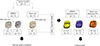
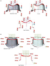
With the generated STL file, the PEKK framework was milled five times with a four-axial milling machine (Cendres+Métaux SA, Biel-Bienne, Switzerland). With the milled Pekkton framework, five PCs were created by framing the external form of the crown with a microhybrid resin composite (Gradia Direct; GC Corporation, Tokyo, Japan), according to the manufacturer's instructions (Fig. 1).
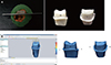
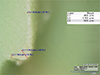
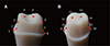
After creating five samples for each group, the SRT method was used to measure the marginal and internal gaps of each crown. Light-body silicone (Aquasil Ultra XLV Regular Set, Dentsply Caulk) was placed into a dental silicone gun (MixPac, Dentsply Caulk) with a 1:1 mixture of base and catalyst. The silicone was injected between the internal region of the crown and the model through an impression tip that was applied with finger pressure and an Instron universal testing machine (Instron 3345 Tester, Instron, Norwood, MA, USA), which was tested at 50 N. After 5 minutes, the crown and model were separated and the heavy-body silicone (Aquasil Ultra Rigid Regular Set, Dentsply Caulk) was placed into the same gun and injected into a round-shaped tray before embedding the replicated light-body silicone. To measure as a fixed part, two epoxy models were created by inserting epoxy (Modralit 3K, Dreve Dentamid GmbH, Unna, Germany) after replicating the master model. A customized jig was manufactured for one epoxy model cut in a buccolingual direction, while the other model was cut in a mesiodistal direction. The silicone replica was cut on these jigs with a razor blade (Fig. 2A). To measure the space between the model and the crown in the light-body silicone replica,2529 the silicone replica was observed under a digital microscope (KH-7700, Hirox, Tokyo, Japan) at 160× magnification (Fig. 3). The measuring point of the marginal and internal gaps (16 points) was then determined (Fig. 4). One experienced dental technician was involved in the measurement. As it involves a potential bias such as morphological and rounded margins, it is practically necessary to determine the number of measurements, given that it is difficult to describe a certain gap with only one measurement point.30 Therefore, the measurement points in the current study were selected according to the contour difference of the crown and the abutment.30
The marginal gap (points 1, 8, 9, and 16) is the vertical discrepancy between the margin preparation and the crown. The deep chamfer (points 2, 7, 10, and 15) is the vertical discrepancy between the crown and the point where the margin changes to the axial wall. The axial wall (points 3, 6, 11, and 14) is the center of the cusp and between the deep chamfer, and the occlusal area (points 4, 5, 12, and 13) is the point of the trisection portion of the occlusal area's cusp.
The 16 measuring points included those for the marginal gap (points 1, 8, 9, and 16), rounded chamfer (points 2, 7, 10, and 15), axial wall (points 3, 6, 11, and 14), and occlusal area (points 4, 5, 12, and 13).
The 2-D sections of the 3DSA were utilized as a new verification method. This is a method for measuring the section deviation, which is the deviation between the reference data and the scan data for the entire area in the unit surface. In addition, the deviation from a particular location and the variation in the cross section above the whole area were measured (Geomagic User Guide and Tutorial, 3D Systems Inc., Rock Hill, SC). For optical scanning, powder (Entwickler Nr. 3, Helling GmbH, Germany)31 was spread on the required area of the PMMA (Pekkton Ivory, Cendres+Métaux), the stone cast of an abutment tooth, and the internal side of the 15 crowns. These were scanned with an optical scanner (Smart Scan R5, Breuckmann GmbH, Meersburg, Germany)3233 with a feature accuracy of less than 7 µm (Fig. 1) and saved as STL files. The abutment tooth of the master model (reference STL, nominal data) and the internal region of the crown (scan data) were alignment-transformed with a 3-D inspection software (Verify, Geomagic GmbH, Stuttgart, Germany) with the obtained STL file. The three-dimensional evaluation method is based on the basic principle of the merging software, which is to mathematically find the best fit for the abutment teeth and dental prostheses at the closest distance.343536 Therefore, accurate merging on one surface can cause errors on other surfaces due to compensation, which does not allow the representation of realistic cement values.343536 In this study, alignment transformation was performed to compensate for this. The x, y, and z axis planes of the object to be compared are formed without being shifted to one side, and the planes corresponding to the axis are uniformly merged (Geomagic Verify User Guide). The alignment-transform function of the scan data can be manually transformed to the nominal data by picking pair points or using a manipulator. This method is used to turn the scan data into nominal data when the auto alignment method does not produce the desired results. The transform command also supports the use of a transformation matrix if the user already knows the specific transformation values (Geomagic Verify User Guide). To accurately measure the gap between the external region of the model and the internal region of the crown, a model-conjugated abutment tooth was cut in the buccolingual direction and another tooth was cut in the mesiodistal direction by using the function of multiple sections after the whole digital deviation (Fig. 2B). The measurement area of the marginal and internal gaps (16 points) was then measured by applying the 2-D section (Fig. 5). The measurement procedure was repeated in the same measurement area as that used in the 3DSA performed with the batch process method. The batch process is used to replace only the scan data file corresponding to the entire process overlapping the nominal data and scan data because they perform the whole process exactly.
The marginal and internal gap values were not normally distributed according to the Shapiro-Wilk test of normality (P < .01). The 16 points were categorized into four regions as follows: marginal gap (points 1, 8, 9, and 16), deep chamfer (points 2, 7, 10, and 15), axial wall (points 3, 6, 11, and 14), and occlusal area (points 4, 5, 12, and 13). A nonparametric version of the two-way analysis of variance with rank-transformed values was used to compare the gap in each region. For the marginal gap, deep chamfer, and axial wall, the interaction between the measurement type and fabrication method was not significantly different (P > .05), and a main-effects model was used to investigate the differences between the regions. For the occlusal area, the interaction between the measurement type and fabrication method was significantly different (P < .05), and a full factorial model was used to investigate the differences between the regions. The Tukey's honest significant difference (HSD) test was used for post-hoc comparisons. A sample size of 5 per group was determined using G*Power,37 assuming an effect size of 0.74, an alpha level of 0.05, and a minimum power level of 0.81. The type I error level was set at 0.05.
All statistical analyses were performed with the Statistical Package for Social Sciences software (SPSS v 21.0, IBM Corporation, Armonk, NY, USA).
RESULTS
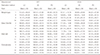
Table 1 shows the mean (± standard deviation) marginal and internal gaps of the molars for each fabrication and measurement method. Significant differences in the marginal gap (P < .010), deep chamfer (P < .001), axial wall (P < .001), and occlusal area (P < .001) were observed between the fabrication methods. A significantly greater difference in the occlusal area was observed between the measurement methods (P < .030). No significant differences in the marginal gap (P > .350), deep chamfer (P > .719), and axial wall were found between the measurement methods (P > .150) (Table 2).
The Tukey HSD post-hoc test revealed no significant difference between the LC and ZC, or between the ZC and PC. However, the marginal gap region was significantly larger in the LC than in the PC (Table 2). The LC and ZC did not significantly differ in terms of their deep chamfer regions, but the LC had a significantly larger deep chamfer region than both the ZC and PC. The axial wall region of the ZC was significantly larger than that of the LC, which was significantly greater than that of the PC. The LC and ZC did not significantly differ in terms of their occlusal regions, and the PC had a significantly smaller occlusal region than both the LC and ZC. The Tukey HSD post-hoc test revealed that the SRT and 3DSA were significantly different only in terms of the occlusal region.
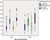
The PC exhibited the lowest values in all the regions when both the SRT and 3DSA measurement methods were used. In the marginal gap and occlusal regions, the following order was observed for both the measurement methods, (high to low) LC, ZC, and PC. In the deep chamfer region, the order was the same with the SRT measuring method; however, with the 3DSA measurement method, the following order was recorded, (high to low) ZC, LC, and PC. The same order was observed in the occlusal region when both the measurement methods were used (Table 2). The 3DSA measurement method showed a larger mean value distribution than the SRT measurement method (Fig. 6).
DISCUSSION
The purpose of this study was to assess the marginal and internal gaps by using three different fabrication methods in order to evaluate the potential clinical applications of PEKKs. We observed a significant difference in the marginal and internal gaps between the different fabrication methods across all the regions. Based on the results of the comparative evaluation of margin fitness for the two measurement methods, the null hypothesis was rejected because the measurements in the occlusal region showed significant differences between the methods. The significant difference in the occlusal area between scan and silicone is due to the limited scanning of the crown area owing to the technical characteristics (some scanners cannot scan deep and narrow structures) of the scanner.38
This study demonstrates that in terms of the marginal fitness, the PC is a more suitable option than the other two fabrication methods. With the LC and ZC, contraction during sintering appears to have a negative effect during the manufacturing of dental prostheses.7 PEKK crowns should show better fitness because of the absence of a sintering process and, therefore, of contraction. Furthermore, both the LC and ZC exhibited positive and negative errors in the inner face generated during the process of combining the digital impressions of the crown. These findings support those of previously published studies on this topic.29303132333435363738394041 The quantitative evaluation of the marginal adaptation is not yet standardized and can be misleading.42 According to Guess et al.,43 100 µm is the clinically acceptable marginal gap for ceramics, while McLean and von Frauenhofer reported a gap of less than 120 µm.44 Another previous study reported that 100 - 200 µm is the clinically acceptable range for long-term preserved dental prostheses.45
The present study showed that in terms of the occlusal region, the LC measured with the SRT, and the LC and ZC measured with the 3DSA exceeded the clinically applicable range of marginal adaptation (Table 1 and Table 2). This was because the corner site of the occlusal surface of the molar region was not an exact reproduction (indicated by the positive and negative errors) due to the bur diameter limitation at the undercut site.146 However, the measurement value of the occlusal region in the present study was clinically acceptable according to previous reports.284647 Anadioti et al.21 reported a marginal gap for the LC by the SRT of 74.00 ± 26.00 µm and for the LC by 3DSA of 84.00 ± 24.00 µm. Hamza et al.48 reported a vertical marginal gap of 40.20 ± 6.70 µm for lithium disilicate material and 86.10 ± 28.80 µm for zirconia. Meanwhile, Bayramoğlu et al.28 confirmed a vertical marginal gap of 109.30 ± 46.40 µm for zirconia. In the present study, the marginal gap region was in the clinically applicable range because with the SRT, the marginal gaps were 96.49 ± 51.01, 77.06 ± 32.14, and 66.83 ± 22.31 µm for the LC, ZC, and PC, respectively. With the 3DSA, the marginal gaps were 99.05 ± 55.63, 96.87 ± 51.68, and 63.76 ± 29.63 µm, respectively. The deep chamfer and axial wall regions were also in the clinically applicable range. Therefore, the LC, ZC, and PC may be considered clinically applicable (Table 1 and Table 2).
Multiple verification methods are available for fitness measurements, including 1) the measurement of the margin between an abutment tooth and a dental prosthesis under a microscope,49 2) the measurement of a cut cross section using an electronic microscope after embedding an abutment tooth and a dental prosthesis conjugated with resin or epoxy,50 3) the SRT that replicates the distance between a dental prosthesis and an abutment tooth or a model with light-body silicone and sustains the form with heavy-body silicone before measuring the cut cross section of interest,722232444 4) and micro computed tomography to measure the fitness through observations of the internal section of the dental prosthesis.51 Among these methods, the SRT has been widely utilized owing to its proven credibility and validity.24 The present research utilized a new verification method, the 2-D section of the 3DSA, which involves the measurement of the gap by overlapping a scanned abutment tooth external surface and a scanned dental prosthesis internal surface. To verify this new method, we compared it with the SRT. The SRT produced more stable values with lower minimum and maximum values, and standard deviation range than the 3DSA. The SRT method requires making a silicone replica for each measurement, so when the marginal gap between the bucco-lingual section and the mesio-distal section has to be measured, two silicone replicas have to be made. This means that two different silicone replicas are measured. In contrast, with the 3DSA method, the same internal gap can be measured (Fig. 6). However, considering the statistically significant difference only in the occlusal region, the SRT is clinically applicable for the remaining regions (Table 1).
The following limitations of this study need to be discussed. First, the scans of the interior surface of the prostheses had errors, indicating errors in the course of the prosthesis treatment and software application. Studies on intraoral scanning by Jeong et al.52 in a complete-arch model showed excellent precision as compared to a Blue light scan, which showed scanning errors. And to be increased before and after the sintering had an impact on the precision shrinkage error. Some errors may have occurred in the diameter sizes, milling axis of the design, milling bur using the software, and additional processing steps and affected the precision.53 In addition, the small gap values of the PC should not be overly emphasized. Second, unlike with the SRT, with the 3DSA, repeated measurements had to be performed at the same site if a few outliers were observed on the histogram, as indicated by the stable ranges (Fig. 6). However, compared with the 3-D superimposition 2-D verification methods, the SRT is still insufficient for length measurements. As seen in Figure 6, the measurement of the internal gap has a larger range in the 3DSA group for almost all the areas (both the 50% interval and 25% quartiles are larger). Nevertheless, this study is significant because the methods used involved cutting, and verification requests were made if the same site was considered.
CONCLUSION
The three fabrication methods exhibited marginal gaps within the clinically acceptable range. Although the SRT and 3DSA measurements of the occlusal region significantly differed, no significant differences were observed for the other regions. Thus, both the measurement methods are applicable as verification methods of marginal and internal adaptation.

 XML Download