

 PDF
PDF ePub
ePub Citation
 Print
Print


INTRODUCTION
Successful replacement of metal-ceramic dental restorations by all ceramic core-veneer restorations has long been one of the goals of scientific dental research. Biocompatibility, appearance, and patient demand1 are apparently the most important reasons. The durability and effective long term service of all ceramic systems especially in load bearing situations have yet to be proven.234 Few long term clinical studies56789 are available to fully evaluate the performance and life span of newer all ceramic systems for both single and multiunit dental restorations.
The interfacial integrity and the reliability of the bond between the high strength core and the weaker veneering material are directly related to the mode of failure of all ceramic restorations.101112131415 The physical, chemical, and mechanical properties of core and veneer materials can significantly affect the interfacial bonding.10121617 Previous researches have mainly focused on the strength and failure modes of ceramic bilayers utilizing macro-mechanical testing.161819202122 Nanoindentation is a research tool with numerous applications in the dental field for both natural dental hard tissues and restorative dental materials.23242526 Quantitative data from the resin-dentin interface2327 suggests that nanoindentation is a potentially useful tool for the evaluation of the bond acquired. Nanoindentation derived properties from the interfaces of restorative dental materials can also be utilized in numerical models to aid in the understanding of the load transfer within a restoration.252628
High strength yttria stabilized zirconia (YTZP) core systems are commercially available for manufacturing dental crowns and bridges after veneering with sintered or heat pressed dental glass-ceramics. Core-veneer matching of modulus of elasticity (E) plays a major role in the success of dental ceramic bilayers, as abrupt E and toughness changes can cast adverse effects on the survival of such restorations.1029 Depending on the veneering material and/ or on the YTZP core system used, an interlayer is usually used to modify the appearance of the core material and to theoretically improve the bonding between the core and the veneering material. It has, however, been suggested that such interlayers may not enhance the resultant bond.131430 Wang et al.30 found that the interface toughness was reduced in YTZP specimens lined with an interlayer prior to veneering. Nanoindentation across such multi-layered ceramics and E mapping at and across these interfaces could provide further important information on the efficacy of these systems. The aim of this study was therefore to test the modulus of elasticity (E) across the interfaces of veneered dental YTZP ceramics using nanoindentation.
MATERIALS AND METHODS
All-ceramic veneered specimens (YTZP core plus veneer) were produced as follows. Rectangular specimens (10 mm length × 5 mm width × 1 mm depth) were sectioned from an yttria-stabilized (5 wt% Y2O3) zirconia powder blank (ZS blank, Lot No. LA100691445, KaVo Everest, Biberach, Germany) using a diamond disc (Cutman 100, No 1575202, Girbach Dental, Germany). The sections were sintered in a pre-programmed furnace (KaVo Everest Therm, KaVo, Biberach, Germany) overnight at 1500℃ according to manufacturer's instructions. One surface of the sintered YTZP sections was manually wet lapped in a special steel mould to 1000 grit silicon carbide paper mounted on a grinder-polisher (Struers Knuth-rotor 3, Struers, Ballerup, Denmark), to achieve a depth of 0.5 mm. The specimen depth was selected to reflect a realistic dental restoration core thickness. At the end of the lapping procedure, the specimens were ultrasonically cleaned (Transsonic 310 Elma, Singen KN, Singen, Germany) for 2 minutes and steam cleaned. A ceramic interlayer material (IPS e.max ZirLiner powder, Lot No. H29042, Ivoclar-Vivadent, Schaan, Liechtenstein) was mixed with IPS e.max Ceram all-round Build up Liquid (Lot No. H32800, Ivoclar-Vivadent) and was used to coat the unlapped sintered YTZP surfaces of two YTZP specimens (Type-1 specimens). The Type-1 specimens were then vacuum fired according to manufacturer's instructions (Table 1A) in a porcelain furnace (Multimat MCII, Dentsply, Weybridge, UK). An even layer of wax (S-U modelling wax, Schuler-Dental GmbH &Co, Germany) was applied to the surface of the sintered ceramic interlayer (IPS e.max ZirLiner) of the Type-1 specimens and the as-sintered surface of the Type-2 (no interlayer) YTZP specimen using a special steel mould to a total specimen thickness of 1.65 mm. A wax sprue (3 mm in diameter) was attached with one end to each specimen at a 45° angle and the other end to a large investment ring base fitted with a surrounding silicone cylinder. The specimens were then invested using manufacturer's recommendations for crowns: 200 g of investment material (IPS Press Vest Speed powder, Ivoclar-Vivadent) mixed using 32 mL of investment liquid (IPS Press Vest Speed liquid, Ivoclar-Vivadent) and 22 mL of distilled water in a vacuum mixer (Multivac compact, Degudent, Hanau, Germany) for 2.5 minutes. After setting for 40 minutes the refractory investment cylinder was transferred to a preheated burnout furnace (5365, KaVo EWL, Biberach, Germany) at 850℃ and held for 1 hour. The preheated cylinder was removed from the furnace and two room temperature glass-ceramic ingots (IPS e.max ZirPress ingots, Lot No. H21335, Ivoclar-Vivadent) and an alumina plunger (23℃) were inserted into the refractory muffle. The refractory was next transferred to a preheated pressing furnace (Cerampress Ney, Jeneric Pentron, Wallington, CN, USA), and the glass-ceramic ingots were extruded into the refractory using the manufacturer's heat pressing settings (Table 1B). Following heat pressing, the refractory was removed from the pressing furnace and left to cool to room temperature. The pressed components were divested using 50 µm glass beads at 2 bar in a grit-blasting machine (Renfert Basic Quattro IS, Renfert Gmbh, Hilzingen Germany). The specimens were subsequently immersed in hydrofluoric acid solution (IPS e-max Press Invex Liquid, Ivoclar-Vivadent) in an ultrasonic bath (Transsonic 310 Elma) for 5 minutes to remove any reaction layer formed during heat pressing. After water rinsing for 1 minute, the specimens were separated from the sprues via a diamond disc with the low speed (15000 rpm) under water lubrication. The glass-ceramic surface of all specimens was lapped to 1000 grit silicon carbide paper to a specimen thickness of 1.5 mm and ultrasonically cleaned for 2 minutes. The specimens were then subjected to two stain firing cycles according to manufacturer's instructions (Table 1A). The veneer of the specimens was glazed using IPS e.max Ceram Glaze paste (Lot H24056, Ivoclar-Vivadent) and the firing parameters in Table 1A.
The layered specimens were mounted in epoxy resin separately (Epofix, Struers, Copenhagen, Denmark) as follows: a) 1 × Type-1 specimen (for preliminary Nanoindentation test); b) a pair of 1 × Type-1 and 1 × Type-2 specimens (for final Nanoindentation test). The specimens' core-veneer interfaces were exposed and polished on wet 500, 800, 1000 and 2400 grit silicon carbide papers mounted on a grinder-polisher (Struers Knuth-rotor 3). Final finish was achieved on a napless cloth impregnated with a 1 µm fine particle diamond suspension (Hyprez Liquid Diamond type K Standard concentration, Batch 2028, Engis Corporation, Wheeling, IL, USA) under lubrication (Hyprez Fluid, Engis Corporation, Wheeling, IL, USA) on a polishing unit (Kent 3 Automatic polishing unit, Engis Ltd., Oxon, UK) at 150 rpm for 5 minutes. The specimens were washed with detergent under running water and ultrasonically cleaned in water for 5 minutes.
Preliminary testing took place across the interface of a Type-1 specimen to determine the load for the final mappings. An ultra-micro indentation system (UMIS) CSIRO 2000 (ASI, Canberra, Australia) was used. Prior to indentation, alignment between the indenter tip and the on-stage microscope was performed using the × 20 objective lens to accurately target the area of indentation. The mounted Type-1 specimen was bonded to a metal base using a cyanoacrylate adhesive and transferred to the magnetic stage of the UMIS. The UMIS applied a force on the tested material through a diamond indenter and recorded its penetration depth. Measurements were performed using a spherical diamond indenter with nominal tip radius of 5 µm. The multiple point load - partial unload method was used313233 in which, for each indentation site, the maximum force was reached in 40 increments. An E value was measured from the load - partial unload stress-strain curve of each increment. Forty E values were thus recorded for each indentation site. The partial unloading fraction in this study was set to 75% for every force increment. As explained in detail by Field and Swain,31 the indentation modulus (E*) is calculated using:
where Pmax is the maximum load applied, α is the radius of contact, and he is the elastic penetration depth. The material modulus (Em) is then calculated using the relationship between indentation modulus (E*), indenter modulus (Ei), and material modulus:32,33
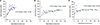
where νm and Em are the Poisson's ratio and the E of the material, respectively, and νi and Ei are the Poisson's ratio and the E of the indenter, respectively. A common value of 0.22 for the Poisson's ratio was used for the tested materials.29 The Ei and νi of the diamond indenter used were taken as 1150 GPa and 0.07.34 An indentation layout file was created, the schematic of which can be seen in Fig. 1A to accurately map the desired indentation sites across the interface. A total of 21 indentation sites were indented. The data retrieved were corrected for variations in the diamond indenter tip radius using a tip function previously obtained by calibration using four reference materials (glassy carbon, sapphire, silicon, and fused silica).35 The corrected data were further processed to plot graphs of E versus depth below contact for every indentation site.
The test was then repeated for the Type-1 and Type-2 pair of specimens using the optimal load (50 mN) determined previously. The new indentation layout file can be seen in Fig. 1B. 21 indentation sites were indented on each specimen during one nanoindentation session. The data retrieved were again corrected for tip function and further processed to plot graphs of E versus distance from the core-veneer interface. A one-way ANOVA test (SigmaStat, ver. 2.03, SPSS Inc., San Jose, CA, USA) was used to statistically compare the near-interface changes in E. A compound optical microscope (Olympus BX 60, Olympus Optical Co., Ltd., Tokyo, Japan) was used to verify the location of the indents.
Suitable specimens for all the materials used in the study were fabricated and prepared for Scanning Electron Microscopy (SEM). ZirLiner (IPS e.max ZirLiner, Ivoclar-Vivadent) powder was used to fabricate a disc specimen by moistening 1 g of powder with IPS e.max Ceram alround Build up Liquid (Ivoclar-Vivadent) and compacting in a hollow cylinder mould with a plunger. The ZirLiner disc was then sintered by receiving one ZirLiner firing, followed by two stain and one glaze simulated firings (Table 1A). A YTZP section (ZS blank, KaVo Everest) was cut and sintered as previously described. It then received the same firing cycles as the ZirLiner disc specimen. A ZirPress specimen (IPS e.max ZirPress, Ivoclar-Vivadent) was produced by investing a 3 mm diameter wax sprue, followed by the heat pressing and divesting route described previously. The ZirPress specimen then received the same firing cycles as the test specimens (two stain and one glaze firings, Table 1A).
All 3 specimens were embedded in epoxy moulds and polished sequentially, as previously described, to a final finish of 1 µm. The YTZP specimen was then separated from the epoxy in order to be thermally etched. This specimen was placed at room temperature in a furnace (Severn Furnace 1800°, Severn Thermal Solutions, Bristol, UK) and heated to 1450℃ at a rate of 10℃/min, where it was held for 30 min. It was then quenched to room temperature in air.36 The IPS e.max ZirLiner and the IPS e.max ZirPress specimens were etched with a 1% hydrofluoric acid solution for 60 seconds and subsequently washed under running water for 1 minutes and dried. All three specimens were gold coated in a sputter coater (Balzers ScDo5o Bal-Tec, Liechtenstein) at 40 mA for 100 seconds. A Field Emission Scanning Electron Microscope was used (JEOL JSM-6300F, Hertfordshire, UK) in the secondary electron imaging mode (10 KV) and images were acquired from all 3 specimens.
X-ray powder diffraction (XRD) was carried out on all the specimens produced for the SEM. The IPS e.max ZirLiner and the IPS e.max ZirPress materials were ground into fine powders. The sintered YTZP specimen was examined as a solid specimen to avoid potential phase transformation from the grinding process. Bragg-Brentano flat plate geometry θ/θ and Ni-filtered Cu Kα radiation (λ1 = 1.54059 Å and λ2 = 1.54444 Å) was used in an X'Pert-PRO diffractometer (PANalytical B.V., Almelo, The Netherlands). Data were continuously collected with an X'Celerator solid state multistrip detector from 5° to 120° (2θ range), with a step time of 200 seconds and a step size of 0.0334°. Phase analysis was carried out with PANalytical X'Pert HighScore Plus software using the International Centre for Diffraction PDF-4 database.
RESULTS
The graphs in Fig. 2 are the selected E versus depth of penetration graphs from the preliminary testing of the YTZP side only of the Type-1 specimen. Each E data point has been derived from each of the 40 incremental load - partial unload steps. The representative YTZP surface indentation sites tested at 10, 30, and 50 mN loads are presented here, showing how increasing the indenter maximum load influences the scatter of the acquired E values as the indenter proceeds deeper into the tested material.
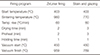
The results of the final E tests across the interfaces of the Type-1 and 2 specimens are presented in Table 2. The mean and standard deviation (SD) of E values of the last 20 data points (partial unloadings) from each indentation site (3 indentation sites per distance) were used to plot graphs of E changes across the interface for both Type-1 and 2 specimens (Fig. 3). E data were analyzed using a oneway analyses of variance (ANOVA) (SigmaStat, ver. 2.03, SPSS Inc., San Jose, CA, USA) and the differences found were significant (F test; P < .001). The values were grouped according to distance from the interface for both Type-1 and Type-2 specimens giving a total of 60 values per distance. The distance groups were compared using Tukey's multiple comparison tests (P < .05). The highest mean E values were all the values on the YTZP, which were significantly different (P < .05) to the interface and veneer E values of the Type-1 specimen (Table 2). There was a statistical difference between E values of the interface and the veneering materials (P < .05). Veneer E values at 120 µm (Type-1) were found to have no statistical difference (P > .05) from the 80 µm veneer values but were statistically different with all other Type-1 E values (P < .05) in Table 2. The Type-2 specimen (no IPS e.max ZirLiner) produced the highest mean E at the 40, 80, and 120 µm values on the YTZP, which were significantly different (P < .05) to all the other Type-2 E values (Table 2). There was no significant difference amongst the veneer E values (P > .05). The interface value was significantly different (P < .05) when compared to all other values of Type-2 specimen.
E values for Type-1 and Type-2 specimens were compared for significant differences. The 40 µm E veneer values between Type-1 and Type-2 specimens were found to be significantly different (P < .05). There were no statistical differences for all other E groups.
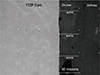
Fig. 4 indicates the near interface indents on the Type-1 specimen. The mean (SD in parenthesis) thickness of the IPS e.max ZirLiner layer (interlayer) at the area of interest was measured as 48 (4.8) µm.
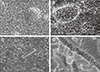
The YTZP specimen showed a high area fraction of fine zirconia grains (Fig. 5A). The IPS e.max ZirPress specimen showed nanoscale fine whiskers densely dispersed in a glassy matrix (Fig. 5B). Larger micro-particulates were sparsely observed in the microstructure (Fig. 5C). The IPS e.max ZirLiner specimen showed only sparse nano-phase particulates (Fig. 5D).
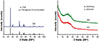
The XRD pattern of the YTZP specimen revealed a bulk tetragonal zirconia phase (Fig. 6). The XRD pattern of the IPS e.max ZirPress specimens showed a bulk amorphous phase and some very small peaks that could not be clearly identified (Fig. 6). The XRD pattern of the IPS e.max ZirLiner showed a bulk amorphous phase (Fig. 6).
DISCUSSION
Specimens were produced so that they would reflect clinical practice in terms of the core-veneer thickness ratio, and the multiple firings were done to simulate the thermal history.10 The YTZP core material to be veneered was left as-sintered for the purposes of this study in order to replicate the surface finish determined by its machining and sintering.37 The YTZP surface to be veneered can be greatly affected by heat treatments and surface finishing38 due to transformation toughening,39 resulting in unconventional interfacial properties.38 While these transformed grains may be restored to their tetragonal configuration after veneering heat treatments, the transformation associated grain volume changes can produce a flawed interface.40
One important advantage of spherical indentation is the absence of significant geometrical variations at the indenter tip. This property particularly facilitates E determination as it renders the initial surface contact elastic.41 E can quite accurately be determined using the single point unload method.32 This method requires relatively low indentation loads and penetration depths and preferably large radii indenters (> 20 µm) so that the contact is purely elastic.33 Using a large radius indenter in this study would have necessitated wider indentation spacings,26 potentially resulting in incomplete mapping of the interfacial compositional gradient. On this basis, a smaller radius spherical indenter combined with the multiple point load-partial unload method was chosen. This method also provides reliable modulus results,3135 by taking advantage of the elastic nature of the unloadings. In order for this to apply, the unloading force fraction has to be set to a value equal to or less than 75%.35 Furthermore, as multiple values are acquired from each indentation site, statistical analysis is greatly facilitated.35
According to Fischer-Cripps,32 spherical indenters are generally sensitive to surface roughness effects that increase the scatter in small penetration depths, and therefore higher loads are recommended. The representative selected E versus depth of penetration graphs from the YTZP side of the preliminary Type-1 tested specimen (Fig. 2) are in agreement with this observation. The 20 last partial unloadings using the highest tested load (50 mN) were therefore considered ample for the determination of the E values for the final testing.
Accuracy of nanoindentation derived data is a matter that depends on various parameters and error sources, which are dealt extensively in the study of Fischer-Cripps.42 In accordance to this study, corrections for machine compliance, initial penetration depth, and tip function were applied in this study. Potential material pile up or sink in should also be evaluated as this can affect measured modulus values.42 The E value reported for KaVo Everest zirconia (Scientific documentation, KaVo, Germany) was 210 GPa, very similar to the values obtained in this study (Table 2). Similarly, Guazzato et al.43 obtained values of 220 GPa for a dental YTZP core material (5 wt% Y2O3) using the standard ASTM methodology (by impulse excitation of vibration). A similar range of values with the E values in Table 2 has also been reported for other dental glass-ceramics from the studies by Lawn et al.44 (between 68 - 69 GPa) and He and Swain26 [65.52 (2.89) GPa], with the latter being measured using a pointed indenter (Bercovich) on a UMIS 2000 nanoindenter. Nanoindentation using spherical indentation and the multiple point load-partial unload method may therefore be a useful predictor of E in this category of materials. In terms of precision, while low standard deviations were obtained for all E values, relatively higher standard deviations were obtained for the YTZP E values than for those of the veneering materials (Table 2). We believe that this potentially may be correlated with the relationship of the sizes of the tip,26 the Hertzian stress field, and the zirconia grains, as well as the orientations of the latter, and thus should be investigated further. Conversely, the low standard deviations obtained for both the interlayer (IPS e.max ZirLiner) and the heat pressed glass-ceramic (IPS e. max ZirPress) materials in all indentation sites (Table 2) suggest that the testing parameters used in this study may be useful for similar applications and materials.
The optical microscopy post evaluation of the indentation areas of the Type-1 specimen (Fig. 4) showed that the 40 µm indents were located within the interlayer (IPS e.max ZirLiner). This finding, coupled with the presence of a statistically significant E difference (P < .05) between Type-1 and 2 specimens at this distance, suggests that the interlayer has a lower E value than the heat pressed veneer. As this does not favor the E gradation across the interface and thus modulus matching,1029 the interlayer may potentially act as a weak link between the YTZP core and the heat pressed veneer. The nano-phase whiskers (Fig. 5B) and the larger micro-particulates (Fig. 5C) found in the heat pressed veneering glass-ceramic (IPS e.max ZirPress) were not categorically matched to a specific crystal type due to the very small, ambiguous X-ray diffraction peaks (Fig 6). The crystallite size and volume fraction may therefore be the influencing factors in this outcome. Höland et al.45 suggested these fibres were fluorapatite crystals. The growth of fluorapatite crystals has been reported to follow an Oswald ripening mechanism, where larger crystals grow at the expense of smaller crystals,4647 and this may be responsible for the larger particulates found within the microstructure (Fig. 5C). Variations in the morphology and volume fraction of these crystals can be expected to affect the optical, mechanical, and thermal expansion characteristics of these materials.46 In this study (Type-1, Table 2) the heat pressed glass-ceramic material produced consistent E values with low standard deviations illustrating material consistency and the reliability of this testing method. The interlayer (IPS e.max ZirLiner) had similar nano-phase whiskers sparsely distributed in the glassy matrix with no large micro-particulates observed (Fig. 5D). Its XRD pattern (Fig. 6) was characteristically amorphous. Therefore further characterization would aid in identifying and quantifying the whisker like phases present in both IPS e.max ZirPress and IPS e.max ZirLiner materials. Links between the resultant difference in the E (Table 2) and the structural characteristics of the two materials may then be possible.
The value on the interface for both Type-1 and 2 specimens shows a significantly lower value (P < .05) than the one obtained for zirconia from the 40 µm distance and a significantly higher value (P < .05) than the one obtained for the veneer from the 40 µm distance (Table 2). Optical microscopy post indentation evaluation revealed possible interfacial line fluctuation, as a result of the nature of the substrate and its' processing (Fig. 4). The values obtained can be attributed theoretically to the fact that the Hertzian stress field, underneath the indents close to the interface, is influenced by both the materials that constitute it, thus giving a mixed modulus reading,2333 and the glass penetration into the zirconia grain boundaries.1448 The relatively larger SD obtained for the interfacial E values in contrast to all the other E values in Table 2 may support these assumptions. According to Aboushelib et al.,14 an inter-diffusion zone exists in bilayer ceramics, where elements (silica, sodium, aluminum, and potassium) migrate into the zirconia substrate extending to a maximum depth of 10 µm of decreasing concentration (Fig. 4). It would therefore be interesting to see whether the potential glass penetration could have yielded this reduction in the E value compared to the bulk YTZP (Table 2). Transmission electron microscopy and energy dispersive X-ray spectroscopy (TEM-EDX) may be useful in the further characterization of these areas. The width of the Hertzian stress field and the subsurface morphology of the interface are however unknown, and need further investigation.
The effect of the interlayer (IPS e.max ZirLiner) in the E reduction seems to stop somewhere between the 40 and 80 µm distances in the veneer of the Type-1 specimen (Fig. 3A), since there is no statistically significant difference (P > .05) between the 80 and the 120 µm veneer E values (Table 2). For the Type 2 specimen, (Table 2) there is no statistical difference in E values (P > .05) between 40, 80, and 120 µm distances on the veneer, indicating consistent E values in the absence of the interlayer (IPS e.max ZirLiner). On the YTZP side of both Type-1 and 2 specimens, 40, 80, and 120 µm E values were also not statistically different (P > .05), and thus no influence of the interface was evident at these distances. Therefore the interesting zone for further work would be between 40 µm or less in the YTZP and a distance equal to a maximum of double the thickness of the interlayer (IPS e.max ZirLiner) in the veneer, since the result in these distances can be technique dependant. In order to sample this zone, where the interlayer material seems to affect E matching, narrower horizontal indent spacings (diagonally arranged in respect to the interface line) could be used, limited by the potential interaction of the stress fields.26 The size of the Hertzian stress field can theoretically be minimized using a smaller radius indenter, but this would be limited by the grain size of the zirconia polycrystals to avoid sampling single crystals. The effect of water storage49 and thermocycling on the degradation of the core and thus on the E matching should also be investigated as it would be more clinically relevant. A good control for these experiments would be a metal-ceramic interface of known successful bond strength. Modulus mappings at this small scale could then be utilized for finite element analysis models2833 to simulate the behavior of dental ceramic multilayers giving insight to the potential failure modes in service.
The coefficient of thermal expansion (CTE) of IPS e.max ZirPress (9.75 ± 0.25 × 10⁻⁶ K-1) (Scientific documentation, Ivoclar Vivadent) may be matched with that of the KaVo Everest Yttrium-stabilized core material (11.5 ± 0.5 × 10⁻⁶ K-1) (Scientific documentation, KaVo). The interlayer (IPS e.max ZirLiner) material presents an intermediate CTE (9.8 ± 0.25 × 10⁻⁶ K-1) and thus should act as a favorable parameter in the gradation of the interfacial compressive stresses preventing interfacial crack initiation and thus failure. It has however been suggested that the application of the interlayer between the YTZP core and the heat pressed veneer in crown/bridge ceramic systems should be avoided as it reduces the bond strength14 and interfacial toughness.30 Our findings also associate a significantly (P < .05) lower E value with this interlayer, which does not favor the gradation of E across the interface, therefore potentially affecting its reliability due to poor modulus matching.1029 All these properties and characteristics, although potentially having a significant effect on the survival of dental ceramic multilayer crown/bridge structures, cannot solely determine their long term in vivo behavior. Many other interfacial characteristics, including wetting,48 microstructure, core-veneer thickness ratio, geometry, processing, thermal history, and porosity,101617 may synergistically affect it. Consequently nanoindentation derived data (E, hardness, fracture toughness50) may render nanoindentation a powerful complementary tool for the evaluation of dental ceramic interfaces.
CONCLUSION
The conclusion of this study associates a significantly (P < .05) lower E value with the presence of an interlayer between the YTZP core material and glass-ceramic veneering material in a multi-layered all ceramic dental restorative system. The present study has shown nanoindentation using spherical indentation and the multiple point load - partial unload method to be a reliable predictor of E and a useful evaluation tool for layered dental ceramic interfaces.


 XML Download