

 PDF
PDF ePub
ePub Citation
 Print
Print


INTRODUCTION
The maxillary posterior area contains cancellous bones with low bone density and thin cortical bones, the quantity and quality of which are lower than those of the mandibular bone. Therefore, it is difficult for implants installed in this region to be stable. This is due to the small implant-to-bone contact area and the inferior bone quality.123 Moreover, the severe bone loss caused by sinus pneumatization or chronic periodontitis, which leads to a reduction in the height of the remaining residual ridge, can further increase the implant failure rate.4 In addition, the occlusal load in the posterior area is 3 - 5 times higher than that in the anterior area.5
To address these problems, various bone graft techniques to augment the insufficient bone volume and thereby ensure the success of maxillary posterior implants have been proposed.6 Such surgical methods have been accepted as clinically meaningful procedures. However, these procedures have a number of disadvantages, such as the invasiveness of the surgery, high cost, and long treatment duration after bone graft and implant installation.6 In addition, because bone resorption occurs after a bone graft, the increase in vertical height is unpredictable. Microscopic studies by Wallace et al.7 suggested that it was difficult to obtain bones with optimal strength from a bone graft. Rosen et al.8 asserted that the success rate of the implant placement after the bone graft depended on the residual ridge height. This was supported by Akça et al.9 who showed that stress applied on the implant was concentrated on the upper part of the implant and that, hence, the stress was not transferred to the grafted bone. Given the above facts and the disadvantages, success rate of bone grafting in a severely atrophied maxilla is not very promising.
Sinus augmentation is a procedure commonly conducted in the maxillary posterior area. Studies have reported that this method may allow new bone formation without the need for bone graft.1011 However, Winter et al.12 stated that the amount of new bone generated by sinus augmentation alone was insufficient and the results were not satisfactory considering the complexity of the technique.
The short implant, not accompanied by additional surgery, is another treatment option. This approach offers many advantages, which include a shorter treatment time, less cost, fewer complications in patients, and minimal surgical invasiveness. Since the introduction of short implant for installation in atrophied residual ridge,13 many previous studies have defined a short implant as measuring 7 mm or less.141516 Although short implants have been reported to have a lower survival rate than standard implants due to the small bone-contact area,1415 their survival rates have increased gradually with advancements in surface treatment technologies.16 As a finite element analysis (FEA) shows that stress transfer at the implant-bone interface is limited to the upper 2 - 3 mm, the long implant is thought to be biomechanically unnecessary.917 Therefore, a short implant may be used for achieving primary implant stability in the case of unfavorable bone quantity and may be used as an alternative for surgical approaches such as bone graft or sinus augmentation.
A molar can endure the occlusal stress more efficiently with multiple roots. Replacement of a missing molar with a single implant may cause various mechanical failures such as screw loosening, screw fracture, and implant fracture.1819 In a severely atrophied maxillary posterior area, using a single wide implant or splinting multiple implants is a way to overcome the unfavorable crown/root ratio of short implants.202122
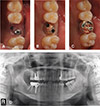
Two-implant-supported maxillary molars with implants installed in buccal and palatal positions were suggested by Balshi and Wolfinger.23 The 2 short implants (2SI, Fig. 1) technique can be used to reconstruct a multi-rooted molar by installing 2 short narrow implants without the need for an additional surgical approach. The 2SI approach is a minimally invasive procedure that solely utilizes residual bones to overcome unfavorable bone quantity and quality in the maxillary posterior area. It can yield stable treatment results while minimizing the need for additional procedures and reducing the cost and treatment time. A 5-year clinical study demonstrated the clinical success of 2SIs.24
The purpose of this study was to compare the stress distribution of various types of 2SIs that were installed and restored in severely atrophied maxillary molar sites. The advantages and limitations of 2SIs were determined from the results.
MATERIALS AND METHODS
An internal connection implant with an 11-degree taper interface was used (GS, Osstem, Seoul, Korea). Internal connection implants (length, 7.0 mm) with narrow platform (NP ø 3.5 mm), regular platform (RP ø 4.0 mm), and wide platform (WP ø 5.0 mm) were modeled. The dimensions of the abutment and implant complex were provided by the manufacturer. Three-dimensional image data of the human maxillary first molar from CT images were transformed into FEA meshes and the connecting area between the crown and implant was smoothened. A gold crown on the abutment (Rigid, Osstem, Seoul, Korea) was connected with the implant. Abutment for each implant diameter was connected, and the occlusal surface area of the definitive prosthesis was constructed to have the same shape.
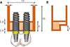
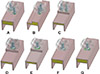
An implant was designed to be installed on the missing maxillary first molar area on the maxilla with a pneumatized sinus, 0.5 mm cortical bone on top and bottom, and 3 mm cancellous bone (Fig. 2). For the boundary conditions, bottom and mesio-distal parts of the maxillary bone were rigidly fixed. The mechanical properties of the bone, gold, and titanium were set as previously described (Table 1).2526 The implant–bone interface was constructed with 100% contact for complete stress transfer to the surrounding bone. Seven implant models were evaluated (Fig. 3). They were broadly categorized into 3 groups of 2SI and 4 groups of single implants. The 2SI groups were categorized into 1) NP oblique (two narrow implants were obliquely installed), 2) NP vertical (two narrow implants were installed in palatal residual bone due to the resorption of buccal bone), and 3) NP horizontal (two narrow implants were installed in distal residual bone due to the mesial bone resorption). Single implant installation groups were set to 1) RP-cantilever (a RP implant was installed in stepped bone due to resorption of the mesial bone), 2) WP-cantilever (a WP implant was installed in stepped bone due to resorption of the mesial bone), 3) RP-center (a RP implant was installed in a flat bone), and 4) WP-center (a WP implant was installed in a flat bone).
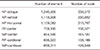
Meshing and pre-processing were performed using Hyper-mesh 10.0 (Altair Engineering Inc., Troy, MI, USA) and Visual Crash for Pam Version 10.5 (ESI group, Paris, France). The number and elements of the finite analysis are shown in Table 2.
Axial and oblique loading conditions were simulated. The average occlusal force, a 250 N static axial load, was applied to the center of the occlusal surface (axial loading). To simulate an oblique loading condition, a 250 N oblique load with a 45° angulation from the implant axis was applied on the center of the buccal cusp (oblique loading). The von Mises stress was measured in the interface of implant-bone, implant/abutment complex, and at the bone of the peri-implant area in all models. To assess the stress distribution, von Mises stress values were visualized using contour plots. The processing and post-processing procedures were performed using PAM-MEDYSA V2014 (ESI group, Paris, France) and Hyper-View V10.0 (Altair Engineering Inc., Troy, MI, USA).
RESULTS
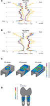
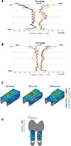
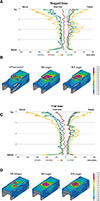
Analyses of stress distribution in the implant-bone interface of an implant in the buccal side (NP-1) showed an evenly distributed stress pattern in the NP-horizontal and NP-oblique groups, whereas the NP-vertical group exhibited a relatively high stress pattern in the top and center areas of the interface (Fig. 4A). In an implant in the palatal side (NP-2), similar stress distribution was observed in the NP-horizontal and NP-oblique groups, while a different stress pattern was observed in the NP-vertical group (Fig. 4B). Stress distribution at the bone of the peri-implant area showed a different pattern to that observed in the interface. The NP-horizontal and NP-vertical groups showed a large stress concentration in stepped areas between different bone levels, while an even stress distribution was observed in the NP-oblique group with flat bone level (Fig. 4C). Few differences in stress distribution of the implant/abutment complex were observed in each group and all stress was concentrated on the interface between the abutment and inner surface of implant (Fig. 4D).
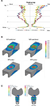
When oblique loading was applied, similar stress distribution was observed at the bone-implant interface of the buccal (NP-1) and palatal (NP-2) implants in the NP-horizontal and NP-oblique groups (Fig. 5A). Although the NP-vertical group showed slightly higher stress concentration, the difference was not as evident as with axial loading (Fig. 5B). An evenly distributed stress pattern at the peri-implant bone was noticed in the NP-oblique group compared with the NP-vertical or NP-horizontal groups (Fig. 5C). The stress distribution of the implant/abutment complex showed virtually no difference in each group, and the amount and location of stress concentrations were similar to those in axial loading (Fig. 5D).
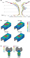
When axial loading was applied, the WP implant showed lower and evenly distributed stress at the implant-bone interface than the RP implant (Fig. 6A). However, the stress difference was not large between the center and cantilever positions. As for the stress on the peri-implant bone, a more even stress distribution was observed in the center position implant than in the cantilever position implant. Lower stress was observed in the WP implant than in the RP implant (Fig. 6B). Stress patterns at the implant/abutment complex of single implants were similar to that of the 2SI groups (Fig. 6C).
When oblique loading was applied, the largest von Mises stress was observed in the RP implant. The WP implant showed a relatively even stress distribution pattern and had a similar level of von Mises stress to that of 2SI groups (Fig. 7A). The stress distribution on the peri-implant bones was similar to that in axial loading but the level of stress was higher. The stress was concentrated on the stepped bone (Fig. 7B). Stress exerted on the implant/abutment complex was very large; a high amount of stress was placed on the abutment and implant in both RP and WP implants. Additionally, larger and wider stress distribution was observed in the implant/abutment contact area on the opposite side of the loading point (Fig. 7C).
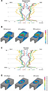
The stress distribution at the implant-bone interface was compared by categorizing the bone levels into two (flat and stepped). When axial loading was applied, higher von Mises stress was observed on the implant-bone interface in the RP implant than in the WP implant or 2SI implants. The highest stress was concentrated on the region with discontinuity between the different bone levels (stepped area) (Fig. 8A). The 2SI groups showed the lowest von Mises stress compared with the RP and WP implants. The area between the implants showed lower stress distribution than the outer side of the implant in 2SI group. The 2SIs showed the most even stress distribution and RP implant showed the largest stress pattern on the peri-implant bones (Fig. 8B). Flat bones also exhibited a similar pattern as the stepped bone (Fig. 8C, Fig. 8D).
When applying oblique loading, the largest stress pattern was noted at the buccal side. Higher stress was observed in the RP implant than in the WP implant or 2 NP implants (Fig. 9A). Stress distribution of the peri-implant bones was relatively small and even in the 2SI groups. A high level of stress was concentrated in the stepped area of the bone (Fig. 9B). Similar trends were observed on flat bones (Fig. 9C, Fig. 9D).
DISCUSSION
To identify the biomechanical effectiveness of 2SIs, various bone levels and bone morphologies were assumed and implants were positioned on the basis of the bone condition. The residual maxillary bone bed was designed with a total length of 4.0 mm and 0.5 mm of cortical bone on the top and bottom for bicortical engagement. Hence, when load was applied on the implant prosthesis, a large stress concentration was observed in certain regions on the bottom cortical bone located on the maxillary sinus side, unlike the result in another FEA study.9 Similarly, in clinical situations, stress may be concentrated on the bottom cortical bone as well as on the top portion in the case of severely atrophied bone.
In this study, the von Mises stress distribution on the bone away from the implant-bone interface was also considered. This is because it was difficult to estimate the effect of stress distribution solely based on the stress pattern at the localized implant-bone interface in case of a severely atrophied bone. In addition, stress on the implant-abutment complex was analyzed to estimate the risk of fracture in a narrow implant.
The single RP implant group showed the highest level of stress at the implant-bone interface. As the diameter of implant used for restoring the maxillary molar is larger in WP, stress is more evenly distributed and general stress amount (in MPa) tends to be lower. Thus, a single NP implant is theoretically the most unfavorable. However, two NP implants exhibited more favorable stress distribution than a single wide implant; this confirms the biomechanical advantage of 2SIs.
In the 2SI groups, the level of stress was not much different between palatal and buccal positioned implants. Meanwhile, NP-vertical, which is a buccal-only or palatal-only positioned condition, exhibited a higher level of stress in the form of a bending moment when axial loading was applied. However, under oblique loading, a similar level of stress was exhibited by the three implant positions (NP-oblique, NP-horizontal, and NP-vertical). These trends arose because oblique loading induced lopsided loading on the buccal or palatal sides. Therefore, the bending moment could be generated in a variously positioned implant, whose diameter is smaller than the roots of a natural tooth.
The stress distributions in the center and cantilever positions of the RP and WP implants did not show a large difference. It may be because adjacent teeth were not modeled and both axial and oblique loading were applied on the mesio-distal center. These results are consistent with previous studies, which showed that the buccal cantilever was the most unfavorable and the mesio-distal cantilever was unfavorable only in terms of oral hygiene.2728
Stress distribution of the peri-implant bone showed similar trends, where von Mises stress was lower in implants of 2SI groups than in RP or WP implants. This may be explained by the contact area between the implant and bone tissue, as placing multiple NP implants is an effective way to increase the contact area. Since installation of a WP implant is difficult in atrophied bones, 2SIs can provide better initial osseointegration and its subsequent maintenance with effective stress distribution.
Stress on the implant/abutment complex was lower than that in the implant-bone interface or peri-implant bones. The stress was concentrated on the contacting surface of abutment and the inner part of implant when oblique loading was applied on RP or WP implants. Clinically, fractures are common in the geometric discontinuity between the upper conical part and the lower hex part of the abutment in internal conical connection implants.29 Moreover, multiple implants can be advantageous since single molar implants exhibit occasional mechanical failures such as screw loosening, screw fracture, and implant fracture,28 and the oblique loading generated even in physiologic mastication can be detrimental to single maxillary implants. In a previous clinical study on 2SIs, none of the NP implants using the 2SI method was fractured.24
The trend of the presence of higher von Mises stress around RP implant than around WP or NP implants did not differ by the bone levels. Prominently, the highest level of stress was exhibited on the stepped area of the bones. This can be viewed as a limitation of the FEA study; stress concentration on the discontinuous area of features is unavoidable in the interpretation of the FEA. In clinical situations, however, these phenomena are not likely to occur as bone loss occurs continuously. In preliminary modeling, the maxillary bone was reconstructed from the data of the patient's CT image. However, real bone images can distort the result when comparing the effect of implant diameter and number. Therefore, over-interpretation of the importance of stress concentration at the discontinuous region should be avoided.
As an alternative to bone graft on a severely atrophied maxillary posterior area, single wide implant or splinting of multiple implants can be performed.2123 The results from the this study showed that, multiple implants, even with a short length and narrow diameter, offer a favorable implant-bone interface, peri-implant bone, and implant-abutment complex. The use of 2SIs, which place NP implants in the most dense bone area in the buccal and palatal sides and utilize residual bones per se without surgical difficulties, is a procedure allowing enhanced osseointegration and favorable stress distribution. However, 2SI could not be used in the case with narrow mesio-distal space.
The results from the FEA study can be the consequence of restricted stress transfer within the 2 - 3 mm of the top of the bone.9 Further, as adjacent teeth were not predetermined, the replication was not identical to the actual situation. Moreover, clinical efficacy cannot be validated solely by a biomechanical study, as only a relative comparison is possible. However, this study is important in that it supports the findings of the clinical study that showed favorable clinical success rates of 180 2SIs.24
CONCLUSION
The stress distributions based on various bone levels and implant installation conditions in a severely atrophied maxillary posterior area were analyzed. When axial loading or oblique loading was applied, the highest level of stress was observed on the implant-bone interface and peri-implant bones in a single RP implant and the lowest stress distribution was exhibited in 2SI conditions. The highest level of stress was concentrated on the implant/abutment-contacting surface of the single wide implant and the lowest level of stress was on the implant/abutment complex of 2SIs. Implant number and position had a larger effect on stress distribution than bone levels.

 XML Download