

 PDF
PDF ePub
ePub Citation
 Print
Print


INTRODUCTION
Appropriate placement of dental implants is essential for esthetic and restorative aspects.12 The development of computer-assisted guided surgery has helped realize restoration-driven implant placement.3 Contemporary guided implant surgery systems are generally based on cone-beam computed tomography (CBCT) and computer-aided design and computer-assisted manufacturing (CAD/CAM) technologies. CBCT visualizes anatomic structures without superimposition, which enables 3-dimensional (3D) diagnosis and treatment planning.456 CAD/CAM technologies improve the fabrication of surgical guides by reducing manual work and facilitating transfer of the planned implant position to the guide template.7 Accurate placement of implants makes it possible to deliver restorations to the patient's mouth on the day of the surgery.89 Accordingly, these advancements have optimized implant treatment to be more predictable, less invasive, and faster from both a surgical and a prosthodontic point of view.1011
Surgical guide templates are categorized based on the extent of drilling restriction.12 Nonlimiting design is simplistic; although such guides serve as imaging indicators for marking the entry point of drilling, they do not limit the angulation or the depth of drilling motion. Thus, nonlimiting design may result in inaccurate implant angulations. Partially limiting design incorporates a component restricting the initial drill used for osteotomy. However, in general, hole enlargement and implant placement are still performed freehand by the surgeon. Most surgical guides with partially limiting design are converted from a radiographic template that is used to evaluate the surgical bone site and devise a surgery plan. Completely limiting design is the most advanced type of guide, restricting the drilling process and placement of implant in three dimensions. This design concept reduces the need for decision making during surgery, thereby leading to more predictable results of implant placement. Contemporary CAD/CAM-based surgical guides are included in this category.1314
The accuracy of a guided implant surgery system is defined as the deviation between the planned and placed position of the implant.15 The accuracy of the entire procedure is a quantitative evaluation of positional and angular discrepancies in 3D coordinates.16 The measurements are performed using image superimposition of pre- and postoperative CT images.17 Possible sources of error include factors such as digitizing, superimposition, machining process, the guide design concept, and the operator's experience. 1819 In a recent in vitro study, Van Assche and Quirynen reported a noticeable tolerance of surgical implant instruments within the metal sleeve.15 This tolerance is caused by the gap between the drill and the guide sleeve, which allows rotation of the drill in the sleeve. Unwanted lateral osteotomy may occur when the drill is not parallel to the sleeve during the drilling; therefore, this type of error is defined as an intrinsic error.20 On the other hand, if there is no tolerance, the friction generated from mechanical components hinders the drilling process, which might result in sleeve deformation.
Recently, a direct drill-guiding implant surgery system with a completely limiting design was developed. This system features shank-modified drills that use the shank portion of surgical instruments as a guiding component to limit drilling motion with little tolerance. Moreover, a guide sleeve is incorporated in the stereolithographic surgical guide design, which eliminates the need for additional insertion of metal guide sleeves into the guide template. The purpose of this study was to investigate the accuracy of this newly developed guided implant surgery system in partially edentulous patients using prospective clinical design and geometric analyses.2122
Go to : 
MATERIALS AND METHODS
Eleven patients (5 men, 6 women; aged 21–75 years; mean age 46 years) requiring implant placements in partially edentulous jaws were included in this study. All patients were treated at the same prosthodontics department of a university hospital. A total of 21 implants (AnyOne; MegaGen Implant, Gyeongbuk, Korea) were placed. 9 implants were inserted in the maxilla, and 12 in the mandible. Patients with a history of debilitating systemic disease or requiring ridge augmentation with bone grafting were excluded from the study. The study was approved by the Institutional Review Board of the hospital (2014-11-020).
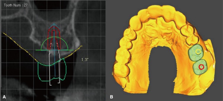
A conventional impression was taken, and a stone cast was fabricated for each patient. The surface image of the cast was then digitized into surface tessellation language (STL) format using a desktop scanner (Ceramill Map 400; Amann Girrbach, Koblach, Austria). Images of the underlying bone were obtained using a CBCT scanner (PaX-Flex3D; Vatech Co., Hwasung, Korea) with a field of view of 120 × 85 mm, voxel size of 0.2 mm, and exposure conditions of 90 kVp, 10 mA, and 24-second pulsed scan. During CBCT image taking, patients were directed to bite a radiopaque Datum tray (MegaGen Implant, Gyeongbuk, Korea) in centric occlusion. The CBCT data were saved in digital imaging and communications in medicine (DICOM) format. The Datum tray was also digitized into a STL file using the desktop scanner (Ceramill Map 400; Amann Girrbach, Koblach, Austria). The solid block portion of the Datum tray was used as a medium for superimposition of the surface image and underlying bone image. The DICOM file and the two STL files were imported into an implant-planning software program (R2GATE 1.0; MegaGen Implant, Gyeongbuk, Korea) where the image merging and virtual surgery were performed. The image-merging process was performed with manual registration by selecting three anatomic landmarks from the dentition. The position of the implant was determined based on the underlying bone and virtual restoration (Fig. 1). After surgery planning, a surgical guide was designed (Fig. 2) and fabricated using a 3D printer (Perfactory 4 DDP; EnvisionTEC, Dearborn, MI, USA).

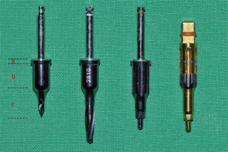
The direct drill-guiding system in this study uses shankmodified drills whose structure has 3 parts: the stopper part, the guide part, and the drilling part (Fig. 3). The stopper structure of the drill corresponds with the stepped structure of the internal surface of the sleeve and restricts the drilling depth when the two structures are joined. The guide part of the drill closely accommodates the sleeve of the guide, which limits the orientation of the drilling motion. The guide part of the drill has the uniform diameter and length; this feature eliminates the need for additional internal tubes. The handpiece connector and ratchet connector are instruments for inserting the implant fixture after osteotomy. As the component for depth control, the handpiece connector has the stopper structure, and the ratchet connector has a horizontal marking to indicate the correct depth of insertion. The sleeve structure of this system is incorporated into the design of the guide template, so the guiding component is created together with the guide body when the template is fabricated (Fig. 4).

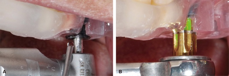
Implant surgery was performed according to the manufacturers' instructions. All patients underwent flapless surgery under local anesthesia with 2% lidocaine. The printed surgical guide was placed over the corresponding edentulous area and adjacent teeth. Implant osteotomy was performed using shank-modified drills (Fig. 5A). Each drilling was performed until the stopper of the drill contacted the rim of the guide template. The implant fixture was inserted using the ratchet (Fig. 5B). All implants were placed by a single operator. To obtain the positional information of the placed implant, postoperative CBCT scanning was conducted using the same settings as the preoperative scan.
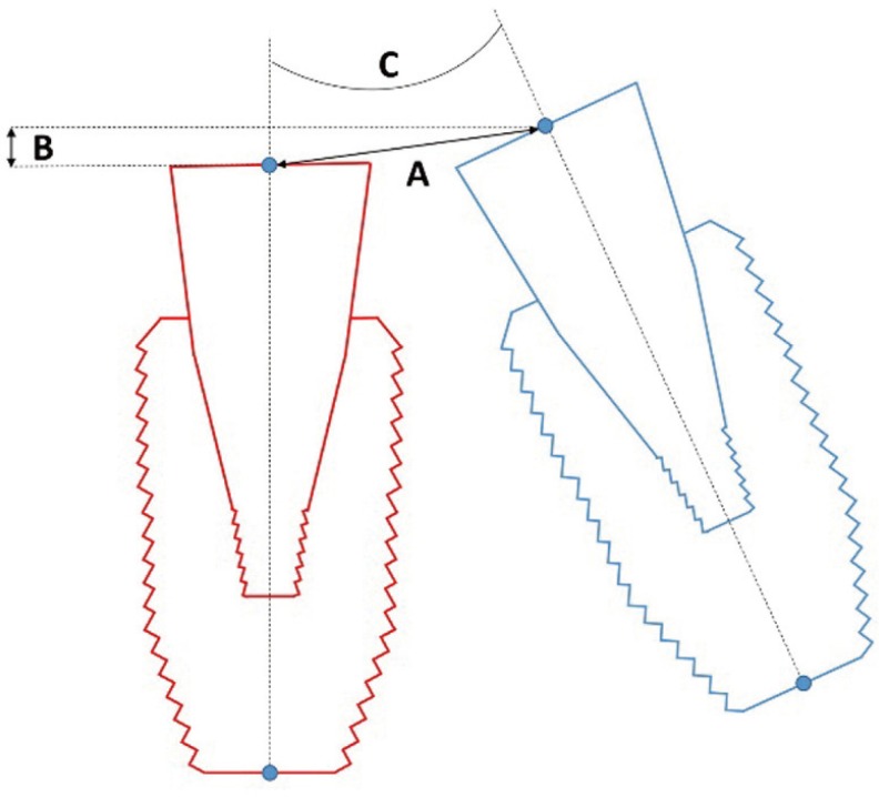
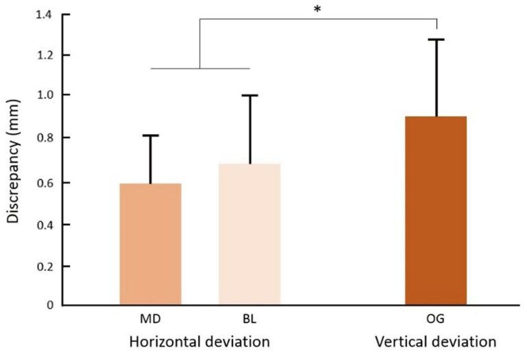
The accuracy of the guided surgery system was evaluated at the abutment level by comparing the virtual abutments of the planned and placed implants (Fig. 6). The planned position of the abutment was determined by the planned position of implant. The actual position of the abutment was determined based on the actual position of the implant in the postoperative CBCT scan. The outcome parameters were horizontal deviation, vertical deviation, and angular deviation, and the values were calculated using the centerlines of the abutments and reference points in 3 dimensions.
All data were reported as the mean ± standard deviation and visualized via bar graphs. The Kruskal-Wallis test and Mann-Whitney U test were used to compare the amounts of deviation among 3 planes. Statistical analyses were performed using SPSS 22.0 for Windows (SPSS Inc., Chicago, IL, USA). A P value < .05 was considered significant.
Go to :
RESULTS
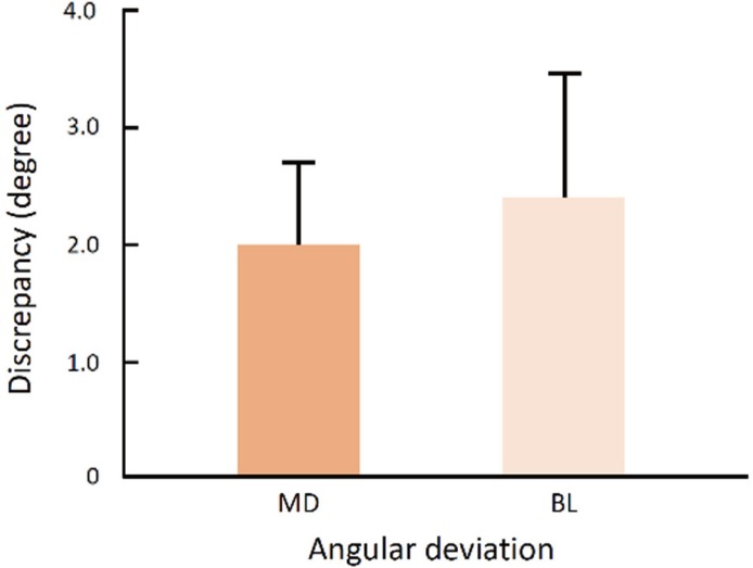
Fig. 7 shows positional deviations between planned and actual abutments. The means and standard deviations of horizontal deviation were 0.593 ± 0.238 mm in the mesiodistal direction and 0.691 ± 0.344 mm in the buccolingual direction. The mean vertical deviation was 0.925 ± 0.376 mm in the occlusogingival direction, which was significantly larger than the horizontal deviations (P = .018). However, there was no significant difference between the two horizontal deviations (P = .421). As for angular deviation, the values were 2.024 ± 0.942 degrees in the mesiodistal direction and 2.390 ± 1.142 degrees in the buccolingual direction (Fig. 8), but the difference was not significant (P = .308).
Go to :
DISCUSSION
The direct drill-guiding system in this study showed higher accuracy in implant placement by using shank-modified drills and a stereolithographic surgical guide that reduces the tolerance of surgical drills inside the guide sleeves. In a recent systematic review, the mean horizontal deviation of implant placement compared to the planned position was reported as 1.2 mm,23 whereas the direct drill-guiding system showed a mean deviation of 0.642; thus, this system is approximately twice as accurate as other systems in terms of horizontal linear deviation. The angular deviation of the direct drill-guiding system in this study was less than the general value of angular deviation reported in the systematic review. These findings correspond well with those reported by Cassetta et al.,14 who evaluated the effects of limiting the tolerance between the drill and guide sleeve on the total error of implant placement. To minimize tolerance, two tubes were used; a guide tube was attached to the head of the surgical handpiece, and a master tube was embedded in the surgical guide. Because the diameter of the guide tube was only 0.05 mm smaller than that of the master tube, these tubes fit closely during the drilling procedure. These mechanics allowed only in-and-out motion, restricting the lateral movement of the drill. As a result, the accuracy of the system with the guide tube was superior to that of the system without the guide tube. The direct drillguiding system in the present study has a similar mechanism for reducing tolerance. Therefore, it can be inferred that the direct guiding components play a key role in limiting drill movement and that tolerance control is essential for increasing the accuracy of the guided surgery system.
Even when the sleeve of the guide template limits the blade part of the drill, a certain amount of gap is inevitable to allow the rotation of the drill within the sleeve.20 The deviation caused by the gap when the drill is not turning can be calculated theoretically by the interrelationship between the sleeve and drill angulation.24 Basically, to increase the positional concordance of the planned and placed implants, it is important to use the drill in a centric position and parallel to the internal wall of sleeve.71525 However, it is not easy to keep a drill in the correct position because visibility and manipulability of the drill is limited in the narrow intraoral space. Meanwhile, the use of longer sleeves has been suggested as a mechanical approach to reduce the tolerance of surgical instruments. Although the above-mentioned parallel drilling and use of longer sleeves are helpful for increasing the accuracy of implant placement, the sleeve should still have some amount of tolerance to prevent friction when the drill is rotating. In other words, the gap between the drill and the guide sleeve is unavoidable, which leads to errors in implant placement. As an alternative for guiding a drilling part of drill through a sleeve, Koyanagi26 suggested the use of two orthodontic wires and tubes to connect the head of the handpiece with the guide template. Since the wires slide along the tube, the drill advances as planned during the osteotomy. Based on this mechanism, accurate and controllable drilling was achieved. The guide system tested in the present study is based on a different working mechanism and consists of modified drills that use the shank part of drill as a guiding surface. Since the guiding surface makes direct contact with the inner surface of sleeve, the tolerance of the drill is markedly decreased. This direct contact can be maintained during drill rotation because both contact parts have smooth surfaces with low the friction coefficient. The combination of the shank-modified drill and sleeve-incorporated stereolithographic guide template therefore completely restricts the implant instruments and leads to more accurate implant placement.
The depth control of instruments is an essential element of a guide system with a completely limiting design.27 The addition of a stopper physically restricts the depth of the osteotomy by allowing drill advancement only to the level of the stopper.2829 This depth control enhances safety by preventing drills from intruding on vital anatomic structures such as the maxillary sinus and inferior alveolar nerve.30 The stopper is also useful for placing the implant at the planned depth, which not only improves treatment convenience but also enables immediate placement of the coronal restoration.31
In general, the mean vertical error of previous implant guide systems was reported as 0.5 mm.19 However, the guide system in the present study showed less accurate outcomes in the depth parameter. This discrepancy seems to be related to the design of the ratchet connector. Although the ratchet connector has a reference line to indicate the stop point, it lacks a physical stopper. Accordingly, the vertical positioning of implant is influenced by the operators' visual and tactile senses. Furthermore, the reference line has a thickness of 0.5 mm. It is assumed that operators did not use the reference line consistently. Thus, to improve the accuracy of this system in the vertical dimension, inclusion of a stopper structure on the ratchet connector is recommended.
The accuracy of guided implant surgery is influenced by procedures that transfer the digital virtual plan to the surgical site.19 Possible individual errors originate from intrinsic sources, which include issues with radiography quality, file conversion, CAD software, and the tolerance between mechanical components; and extrinsic sources, which relate to the fit of surgical guide, the mucosal thickness at the surgical site, the position of the edentulous area, and the surgeon's experience. The accumulation of individual errors produces the total deviation between planned and postoperative outcomes. This study revealed the error in the accuracy of the newly developed guided implant surgery system. Since the data were obtained from clinical cases, the outcome values are clinically valid and meaningful. However, this study did not assess the effects of individual error sources. Thus, controlled in vitro experiments or large-size clinical prospective trials will be needed in the future to analyze these effects.
Go to :
CONCLUSION
To our knowledge, this is the first clinical report to evaluate the accuracy of a direct drill-guiding system for implant placement. The present study confirms that the use of shank-modified drills and sleeve-incorporated stereolithographic templates is an effective way to improve the accuracy of implant placement by minimizing mechanical tolerance of the instruments.
Go to :
 XML Download