

 PDF
PDF ePub
ePub Citation
 Print
Print


INTRODUCTION
Treatment of tooth loss or edentulism with dental implants is very common. However, implant has some complications; problems with implants and the superstructures are common.1 Many complications such as aesthetic problems (ruptures, fractures, abrasions, shade and color changes, or cervical marginal gaps), biological problems (crestal bone loss or osseointegration failure), or mechanical problems (screw loosening or retention loss) may be seen.2
Previous retrospective studies have shown several complications with dental implants, including porcelain fracture and screw loosening.3 Therefore, in case of such complications, retrievability of implant-supported restorations is important.4 Cement-retained implant restorations have advantages including improved aesthetics through avoiding occlusal screw access, reduced prosthetic parts, and simplified clinical/laboratory procedures. Due to these advantages, cement-retained implant restorations are usually preferred over screw-retained restorations by clinicians.567 However, retrieving implant-supported crowns permanently cemented with zinc-phosphate, zinc polycarboxylate, glass ionomer, or self-cure resin cements reveals severe problems.6 Therefore, some researchers suggested using provisional cements as an alternative, to facilitate the restoration removal without harming the adjacent tissues.68910 An ideal cement should have sufficient strength to maintain the restoration in place under function, and it should also enable clinicians to retrieve the restoration without difficulty.4
Once the decision is made to remove the restorations, it is important to protect the implants, the abutments, the abutment screws, and the surrounding tissues during the removal. Clinician's experience, patient's tolerance, type of the restoration, type of the cement used, and the load applied on the implants during the removal are the major factors in deciding the removal method.11
Several literatures have discussed the instruments for crown removal: Richel crown removers, ultrasonic removers, hemostats, and forceps. These crown removal instruments and techniques break the cement seal. These removers apply short, high-impact forces on the restoration. Regardless of the technique used for crown removal, a small force must be applied at the beginning, and if necessary, the force should be increased gradually to protect the implant and the surrounding tissues. Many studies were conducted on the stress distribution of implant-supported prostheses, both fixed and removable. Most of the studies were focused on stresses that occurred during function.3589
The null hypothesis of this study was that crown retrieval has significant effects on bone and the implant complex.
MATERIALS AND METHODS
Three dimensional finite element analysis (FEA) models of a straight implant and an implant with 30-degree inclination were constructed to evaluate the stress distribution and stress concentration levels of a single crown on a mandibular first molar during removal. Graphic processing programs (Rhinoceros 4.0, McNeel, Seattle and Ansys 11.0, Ansys Inc., Canonsburg, PA, USA) were used to construct the mathematical models of cortical and cancellous bones as well as the osseointegrated implant and components.
The geometry for the implant and the abutment was experimental design created for this study. The experimental design was applied because selecting only one design among a great variety of implants on the market would lead to confusion and create questions about the other systems. The implant was modeled with a diameter of 3.7 mm and a length of 10 mm. The abutments had a diameter of 3.7 mm with a length of 4.20 mm. The total axial taper was 6 degrees. Implant-abutment connection was modeled as an internal hexagonal design.
The infrastructure of the crown followed the form of the final restoration and had rounded edges with a minimum thickness of 0.8 mm. The veneering material was porcelain with a thickness of 1.2 mm. Modeling a whole anatomical mandibular body could approximate the physiological conditions. However, a smaller part of the bone was modeled because the study's aim was to evaluate the biomechanical response of the implant components and the surrounding bone during the retrieval of a single implant-supported crown.
Each mathematical model included approximately 14,200 nodes. The calculation of the displacement of each node verified the stress on the structure. The bottom exterior nodes of the alveolar bone in the FEA models were fixed in all directions as the boundary condition. Finer meshes were placed at the interfaces to ensure accuracy of force transfer.
It is impossible to obtain ideal organic material properties, and thus all materials were considered to be isotropic, homogenous, and linearly elastic. The elastic properties (Young's modulus (E) and Poisson's ratio (µ)) were determined by referring to the previous literatures (Table 1).1011 The implants were assumed to be 100% osseointegrated.
A vertical pull-out load of 40 N was applied on the crown margin. The load was determined according to the mean retentive values of previous studies.6 The stress levels were calculated using von Mises stress values, which were commonly reported in other finite element analyses studies. The von Mises stress values compare the stress distribution in ductile materials. The maximum value, in particular, was used as a reference.
RESULTS
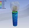
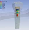
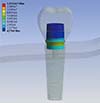
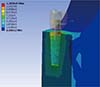
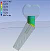
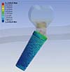
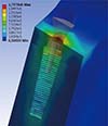
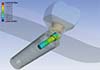
At the straight abutment model, the highest stress was observed inside the implant collar on the implant abutment interface (9.29 MPa) (Fig. 1). The second highest stress concentration level was observed at the 1/3 apical portion of the abutment screw (3.09 MPa) (Fig. 2). The stress concentrations on the abutment and inside the bone were relatively low (1.33 - 1.28 MPa, respectively) (Fig. 3 and Fig. 4).
At the angled abutment model, the highest stress concentration was observed on the abutment collar (7.57 MPa) (Fig. 5). The stress concentration on the implant collar with the angled abutment was also lower (6.11 MPa) than that on the implant collar with the straight abutment (Fig. 6). The stress concentrations at the cortical bone were lower (1.73 MPa) than the stress concentrations inside the implant and related components (Fig. 7). The stress at the abutment screw was concentrated at the 1/3 coronal portion of the screw (3.44 MPa) (Fig. 8).
The highest stress concentration was observed at the collar of the implant with straight abutment. The stress concentrations at the cortical bone were lower than the implants and their components in both models. At the abutment screws, the stress concentration levels were similar but the localizations were different between two models. The stress at the angled abutment was higher than the stress at the straight abutment.
DISCUSSION
Previous studies conducted on stress analysis of implantsupported restorations have focused on stress concentrations and distributions during the procedure of completing the restorations. Furthermore, there are many studies about the retention force of various cements used for crown cementation on the abutments.24612131415 However, no restoration can permanently remain in the oral cavity; thus, they have to be removed for several reasons. Clinicians face this reality every day.
Cementation of the implant-supported crowns has been studied for a long time to distinguish temporary cement from permanent cement. Temporary cements exhibit more failure problems than permanent cements, as expected.81415 The risk of damaging the implant, the implant components, and the superstructures increases when a very strong cement is used. Hence, some researchers suggest initially using weaker cements and then changing them to progressively stronger cements if necesseary.8 Furthermore, the type of the cement and the characteristics of the abutment such as abutment length and taper should be considered. 4816
Our goal was to observe the stress concentrations and distributions at the bone and the implant complex–not the retentive values or resistance values to the dislodgement of crowns. Thus, the type of cement, permanent or temporary, was not distinguished. We used an average resistance value. Although it worked as a limitation of the study, the cement thickness was ignored in the finite element models to simplify the models and to focus on the stress concentrations at and around the implant.311 The abutment angulation also affected the stress concentration levels and localizations.
This outcome was somewhat expected because previous stress analysis studies have reported similar findings of stress concentrations and distributions around implants with different angulations.1718 The angled abutment is a result of implant inclination. It is impossible to load the inclined implant parallel to its long axis, and thus the load acts obliquely and separates into vertical and horizontal components. This horizontal/lateral loading changes the localization and the magnitude of the stress concentrations. In this study, the angulation changes divert the stress concentrations from the implant to the abutment.
According to the previous researches, no cement could be called an "ideal" cement. 281920 Since various cements, cementation techniques, and implant-superstructure combinations are used in those studies. However, the cement must at least be close to ideal and should be sufficiently strong to maintain the crowns in place and weak enough to retrieve easily.281920
As mentioned, FEA is extensively used in investigating the mechanical behaviors of implants, surrounding bone, and other components. Stress analysis methods are crucial in observing and evaluating the behaviors of implants and the surrounding bone under different loading conditions because it is impossible to clinically observe stress distributions. With advancing technology, it has become possible to model complex structures in micro scales.2122 Thus, FEA was preferred in our study. Most FEA studies use static loading to evaluate the stress distributions and concentrations. Dynamic loading can apply 10 - 20% more loading on the implant because crown removal is a dynamic and consecutive load application.1023 This additional load may affect the implant as well as its components, bone, and the superstructures. However, FEA also has certain assumptions. The materials and the bone are considered homogenous and isotropic, and osseointegration is assumed to be 100%, which is clearly different from the clinical reality.
The stress concentrations mostly occur in the cortical bone around the implant collar and in the implant-abutment junction under functional loading.112425 Although cortical bone has a higher elasticity modulus than the trabecular bone and can bear more load, bone loss can be observed at the bone-implant interface under excessive loads. To maintain the alveolar bone, 200 - 700 psi functional stress or a strain value between 1000 - 1500 µɛ is needed. Loads over 3000 µɛ will lead to a pathologic overload and bone loss.10226 In this study, the cortical bone was the least affected element, which was unexpected. The maximum stress at the cortical bone was 1.73 MPa. Thus, it was within the limit of the functional stress and was not at pathological stress levels. It appears that the pull-out force more affects implant components. Thus, the null hypothesis of the study was partially rejected.
The abutment screw is the weakest part of the implant systems. Some previous studies reported that the abutment screw underwent the highest stress concentration.327 Moreover, overloading the abutment screw may lead to loosening or fracture.3 Our results agreed with the previous studies in terms of the direction of the applied force. This indicated that more attention was needed to minimize damage on the abutment screw during the retrieval of a restoration, especially when working with a loosened screw. Any damage of the restorations can be tolerated, but damaging the implant components can be a nuisance.
The implant body and the abutment are relatively bulky components of the implant complex when compared to the abutment screw. However, the implant body can endure the bulkiness at the collar portion as a result of the abutment slot. In this study, the highest stress was observed at the implant collar or the abutment collar. The findings were similar with the previous studies that indicated the stress concentrations occuring at the implant-abutment junction rather than the apical portion of the implants.3 The excessive loads applied on the implants may lead to body fractures.
In addition, the magnitude of the load applied on the implants is important. While excessive forces may damage the restorations, the implants, and the components, they may also lead to a dis-integration of the implant from the bone. In a previous study about the relationship between surface characteristics and removal torque of implants, it was reported that 57-83 N of force was needed depending on the surface micro architecture.28 Thus, the loads beyond these levels increased the risk of dis-integration and implant failure.
The limitations of this study included removal of a single crown as well as the use of only a vertical load. Also, only a single load was applied on the restoration. This may be different from the clinical situations. Further studies should be carried out with multiple implants, longer restorations, and different loading conditions.

 XML Download