

 PDF
PDF ePub
ePub Citation
 Print
Print


INTRODUCTION
The removable partial denture (RPD) path of placement (POP) has been defined as "the specific direction in which a prosthesis is placed on the abutment teeth or dental implant(s)."1 It may also be defined as a set of parallel imaginary axes, such that each atom (or mass element) of the RPD, respectively, will become seated intra-orally, if each mass element moves along an axis from this set, while the RPD is being inserted. One exception to this definition is that RPD mass elements that are part of the retentive termini of clasps follow axes that intersect the occlusal aspects of undercut retentive teeth surfaces, and flex around these occlusal aspects to become positioned into the undercuts during RPD insertion. Also, with a dual-path RPD,2 or an acrylic RPD that during insertion is "wiggled" around tooth obstructions into place, the mass elements follow the axes of more than one POP. A rotational path RPD3,4,5,6,7 follows a set of parallel radial axes during insertion. This article reviews the concept of the RPD POP,8,9,10,11 and describes how to identify an RPD POP for an arch. Other sources provide comprehensive summaries of RPD design.8,9,10,11
This article presents a microscope-based method of developing a general concept of what the RPD POP should be for an arch. This concept helps guide the rigorous surveying of an arch to develop an RPD POP; helps in predicting how a laboratory technician would design an RPD POP for an arch, if the dentist outsources the surveying task to a technician; allows a dentist to detect if projected guide plane surfaces are grossly undercut relative to the projected RPD POP; and aids in verifying intra-orally that contouring of teeth has actually aligned the teeth surfaces to enable the surfaces to provide an adequate RPD POP for that arch.
THE CANDIDATE RPD POP VIEWING AXES
When evaluating, if a specific potential (or "candidate") RPD POP is acceptable among various possible RPD POPs for an arch, a dentist should view a diagnostic or master cast, or the arch intra-orally, using viewing axes that are all parallel to one another and parallel to the axes of the candidate RPD POP, and that all intersect an imaginary plane in space at the same angle. These mutually parallel viewing axes may be called the "candidate RPD POP Viewing Axes." A dentist observing an arch using the candidate RPD POP viewing axes should observe with one eye closed, since, with both eyes open, stereoscopic vision makes it more difficult to evaluate if intra-oral surfaces are parallel with one another, and not undercut relative to the candidate RPD POP viewing axes.
The author advises use of microscope-level magnification of 6-8x or greater,12,13,14 combined with shadow-free, coaxial illumination, when viewing an arch by using the candidate RPD POP viewing axes. Such viewing precision facilitates detecting microscopic deviations in angle of the viewing axes used to view an arch, particularly when observing an arch intra-orally after contouring teeth surfaces, to evaluate if the modified arch provides an acceptable candidate RPD POP, since a mouth mirror used intra-orally may have to be moved vertically and horizontally to position it for viewing, while keeping all viewing axes parallel to one another. When observing a diagnostic model held in hand, this viewing precision facilitates moving the model parallel to only one imaginary plane in space, in order to bring various surfaces of the model in view of the eye that is observing the model using a viewing axis that is fixed to only one angle in three dimensional space. Shadow-free, co-axial illumination prevents surfaces that are parallel to the candidate RPD POP axes from casting shadows when the surfaces are viewed using the candidate RPD POP viewing axes; these shadows can make a parallel surface appear undercut and vice versa.
INITIAL IDENTIFICATION OF A CANDIDATE RPD POP FOR AN ARCH
To identify a candidate RPD POP for an arch, a starting point is to locate a set of candidate RPD POP viewing axes such that all tooth surfaces facing edentulous areas (or, more specifically, all tooth surfaces that are projected to be guide plane surfaces) are parallel to one another. If, on the model or intra-orally, the projected guide plane surfaces of teeth in their current state are not all parallel to the candidate RPD POP viewing axes, then the dentist locates another set of candidate RPD POP viewing axes such that the projected guide plane surfaces appear to be minimally undercut relative to that candidate RPD POP. Here, only minimal amounts of contouring would be required intra-orally to shape these projected guide plane surfaces to be parallel with the axes of the candidate RPD POP. If a dentist views all presently undercut potential guide planes using candidate RPD POP viewing axes, and observes that the apical border of all presently undercut potential guide planes can be made visible with a tiny change in the angle of the viewing axis used to view each respective potential guide plane, then all the potential guide planes can be made parallel with the axes of the candidate RPD POP with minor surface contouring.
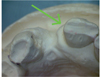
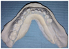
A guide plane surface is parallel with the axes of a candidate RPD POP if the guide plane surface appears 100% foreshortened when the surface is viewed by using the candidate RPD POP viewing axes; that is, the occlusal perimeter of the guide plane appears exactly superimposed on the apical perimeter of the guide plane, when the guide plane is viewed by using candidate RPD POP viewing axes. A guide plane surface is undercut relative to a set of candidate RPD POP viewing axes if the occlusal perimeter of the guide plane surface appears to cover the apical perimeter of the guide plane surface when the guide plane is viewed by using candidate RPD POP viewing axes (Fig. 1). If, either intra-orally or on a diagnostic model, a projected guide plane surface appears heavily undercut when viewed by using candidate RPD POP viewing axes, where a big shift in the viewing angle from the current viewing axes is needed to bring the apical perimeter of the guide plane into view from underneath the occlusal perimeter of the guide plane, then the dentist may have to contour the guide plane surface intra-orally to shape it to be more parallel with the candidate RPD POP axes, perhaps before making a high-precision diagnostic model for surveying.
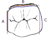
Also, if an arch has an anterior edentulous ridge, the apical-facial line angle of the anterior edentulous ridge should ideally be visible when the dentist attempts to view the apical-facial line angle using the candidate RPD POP viewing axes. This is because, for esthetic reason, the anterior border of an RPD made for an arch with an anterior edentulous ridge, should ideally be able to fully seat into the apical-facial line angle of the anterior edentulous ridge, when the RPD follows the RPD POP while being seated. A set of candidate RPD POP viewing axes where the projected guide plane surfaces are parallel with these axes, and where the apical-facial line angle of the anterior edentulous ridge is fully visible when the apical-facial line angle is viewed by using this same set candidate RPD POP viewing axes, is parallel to the set of RPD path of placement axes that would allow the anterior border of the RPD to seat fully into the apical-facial line angle of the anterior edentulous ridge.
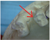
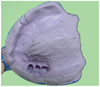
For an arch where there is an anterior edentulous ridge, if the candidate RPD POP that the dentist is assessing, that allows the anterior RPD border to seat into the apical-facial line angle of the anterior edentulous ridge, cannot practically be used as the actual RPD POP (Fig. 2), then the dentist chooses another candidate RPD POP for assessment. The dentist identifies another candidate RPD POP by tilting the cast along the range of an arc of rotation that permits observation of the apical-facial line angle, followed by choosing a specific angle of tilt along this arc and locating a set of parallel imaginary viewing axes that intersect the plane of the tilted arch at the same angle.
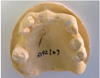
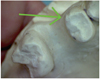
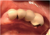
If the patient's smile line does not reveal the apicalfacial line angle of the anterior edentulous ridge, then the dentist may use an RPD POP that allows the RPD anterior border to seat only to the level of the smile line (Fig. 3). A set of visual axes that allows the dentist to observe a line angle on the anterior edentulous ridge that is located at, or is anterior to, the smile line, may be parallel to the axes of a practically usable candidate RPD POP.
If no set of visual axes, that allows observation of this apical-facial line angle, can be identified, such that this set would also be parallel to the axes of a practically usable candidate RPD POP, and the patient's smile line reveals the apical-facial line angle of the anterior edentulous ridge, then it may be technically difficult to fabricate a conventional RPD that would be esthetically acceptable for this patient.
After identifying a candidate RPD POP, the dentist evaluates the candidate RPD POP to determine if it is clinically acceptable for use as the actual RPD POP, by considering the following:
Guide Planes
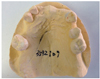
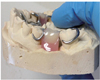
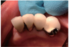
A guide plane is a flat or curved tooth surface such that, after preparing an arch for an RPD and fabricating the RPD, this tooth surface will be parallel to the axes of the POP of that RPD, and such that part of the intaglio surface, of the RPD intended for that arch, will pass slightly laterally to that guide plane surface during seating of the RPD. Such guide plane surfaces may include teeth surfaces that face edentulous areas, the lingual surfaces of posterior teeth, or tooth line angles that face edentulous areas (Fig. 4, Fig. 5, Fig. 6, and Fig. 7). Prior to preparing an arch for an RPD, a tooth surface that a dentist chooses to be a guide plane may be naturally parallel to the RPD POP that the dentist plans for the arch, or can be made parallel with some (ideally minimum) surface contouring. The parallelism of the guide plane to the axes of the RPD POP allows the aspect of the intaglio surface of the RPD, that passes slightly laterally to the guide plane surface, to fit intimately with the guide plane surface. Guide planes also help to prevent lateral movement of the RPD during function, which may improve RPD retention.
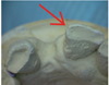
A tooth surface may be parallel to the axes of the RPD POP for its entire apical-to-occlusal length, such that the entire tooth surface is a guide plane. Or, only the occlusal aspect of a tooth surface may be parallel to the RPD POP axes, with the apical aspect of the tooth surface being undercut relative to the RPD POP. However, if a tooth surface contains a guide plane surface aspect only at the occlusal aspect of the tooth surface, an RPD intaglio surface may only be able to fit intimately at the occlusal aspect of that tooth surface. This may result in a food-collecting empty space15 between the intaglio surface of the RPD and the undercut apical aspect of a tooth surface that contains an occlusally located guide plane surface aspect (Fig. 8). This may also reduce RPD retention8 compared to if the intaglio surface can fit intimately with the entire apical-to-occlusal length of a tooth surface, if the entire apical-to-occlusal length of the tooth surface consists of a guide plane surface. For these reasons, any tooth surface, for which it is predicted that the intaglio surface of the future RPD will seat slightly laterally to that surface, should be shaped such that the tooth surface is parallel with, or at least is not undercut relative to, the POP of that RPD.16,17,18,19
Also, aspects of the RPD framework, that extend into edentulous spaces that are bordered by tooth surfaces that are undercut relative to the RPD POP, may have to be made narrower than the actual edentulous space width between the undercut tooth surfaces; if those framework aspects were made to the actual width of the edentulous space, the insertion axes of some mass elements within those aspects would intersect the occlusal aspects of the teeth bordering the edentulous spaces.
If an intra-oral surface is divergent relative to the candidate RPD POP axes, then the occlusal and apical borders of that surface will both be visible when the dentist views the surface using candidate RPD POP viewing axes with the occlusal border appearing to be more axial than the apical border (Fig. 7). The intaglio surface of the RPD will seat on a divergent plane with a slant, giving such seating a slightly occlusal component.
RETENTIVE TOOTH SURFACE UNDERCUTS
The dentist observes the arch using candidate RPD POP viewing axes to verify that sufficient numbers of 0.25-0.5 mm. undercut surfaces (Fig. 9) exist on periodontally and structurally strong teeth to provide RPD retention.8,10 An RPD abutment tooth "undercut" is a line segment on an abutment tooth surface that consists of two points, one more apical than the other, such that the more apical point appears to be more axially located compared to the more occlusal point, when this undercut surface is viewed by using candidate RPD POP viewing axes; this line segment cannot be seen directly, but is "visually apparent" when the dentist attempts to view, using candidate RPD POP viewing axes, all points that are located on the apical border of the undercut tooth surface.20
A dentist can verify if a tooth surface has a 0.25-0.5 mm. undercut by observing that surface using candidate POP viewing axes, and then slightly tilting the viewing axis used to view the surface, until the apical border of the undercut surface, that is normally hidden by the overhanging occlusal border of the undercut surface, becomes slightly visible in the viewing perspective. The surface will have a 0.25-0.5 mm. undercut if the amount of tilt of the viewing angle is in proportion to the degree of angle shift that would make the apical border of the undercut surface visible, if the surface actually was undercut by 0.25-0.5 mm. relative to the candidate RPD POP. Microscopes provide a dentist with the viewing precision that is required to visually estimate undercut values, although a surveyor may be more accurate in this regard.
An RPD clasp terminus that protrudes axially enough to fit into an undercut of greater than 0.5 mm would be too axially protrusive to flex around the occlusal aspect of the undercut tooth surface.8 Consequently, the technician may end the retentive terminus of the clasp no apically than a distance from the occlusal where the slope of the tooth surface reaches a maximum undercut of 0.25-0.5 mm. Locating the retentive terminus of the clasp more occlusally on the tooth increases the leverage forces that the clasp places on the tooth due to the increased distance from the tooth apex.10 An excessively undercut retentive surface may collect food15 apical to the ledge that may be created by the clasp arm.
KEYWAYS AND THE RPD POP
If a dentist can observe the entire perimeter of the apical aspect of a fixed partial denture keyway, if present, using candidate POP viewing axes, then the dentist may create an RPD such that the axes of the RPD POP are parallel with the set of axes that defines this keyway.10 However, if the dentist cannot observe this perimeter completely, then the axes of the keyway are not aligned with the axes of the candidate RPD POP (Fig. 10, Fig. 11 and Fig. 12). The fixed partial denture may be re-made such that the new fixed partial denture keyway axes are parallel to the axes of the candidate RPD POP. Alternatively, aspects of the keyway that appear to be undercut may be blocked out on the model, resulting in a non-intimate fit of the RPD into the keyway. Otherwise, the dentist may reject use of the keyway with that candidate RPD POP, since the parallelism of the RPD POP axes with multiple guide plane surfaces is more important than parallelism with the axes of a small keyway area.
OVERDENTURE ABUTMENTS AND THE RPD POP
If a dentist can observe the complete margins of overdenture abutment/s, if present, while observing the arch using candidate RPD POP viewing axes, then the axes of the POP of the overdenture abutment/s are parallel with the axes of the candidate RPD POP. Therefore, an RPD can be designed to follow this candidate POP while being capable of fitting precisely over the overdenture abutments. However, if the dentist cannot observe the complete margins of the overdenture abutment/s using candidate POP viewing axes, then the axes of the POP of the overdenture abutment/s are not parallel with the axes of that candidate RPD POP. Here, a laboratory technician must block out the overdenture abutment/s on the cast to allow the RPD framework to fit passively over the overdenture abutment/s, so that the overdenture abutment/s do not force the framework to follow a POP that results in the framework being obstructed by other intra-oral structures during insertion. Alternatively, the dentist could re-prepare the overdenture abutments, such that the complete margin/s of the abutment/s are visible when the dentist views the abutments using candidate POP viewing axes.20
RESTS AND INTER-OCCLUSAL CLEARANCE
The dentist observes if there is enough inter-arch distance to place occlusal rests at projected occlusal rest sites.10,11 If such inter-arch distance is inadequate for a specific rest, the laboratory technician must relocate that rest to another site. Such relocation may force use of an RPD POP that is different from the POP which the dentist intended to use, if the dentist intended this rest to be an integral part of a rest, clasp and guide plane assembly, and the dentist shaped a tooth surface accordingly to accommodate the assembly.
MANDIBULAR INCISORS AND THE POP OF A LINGUAL BAR OR PLATE
Some aspects of the incisal one-third of a rotated or lingually inclined mandibular incisor may appear to overhang areas on the lingual anterior gingiva, that are projected seating areas for some mass elements of the framework lingual bar or plate, when the dentist attempts to observe those gingival areas using candidate RPD POP viewing axes. If a laboratory technician designed a lingual bar or plate to seat at that those gingival areas, the mass elements of the lingual bar or plate that would seat at those gingival areas would, during insertion, follow imaginary axes that would intersect the incisal one-third of the incisor. Here, the dentist must reduce the overhanging incisor structures. Otherwise, a laboratory technician would need to design the framework to bypass the overhanging incisor structures; the resulting framework would feature a food-collecting space between the lingual bar and those gingival areas.
INCISOR PROXIMAL SURFACES AND THE RPD POP
An incisor neighboring an edentulous space may be tilted in an anterior direction, such that the facial aspect and proximal-axial line angle of the incisor is heavily undercut relative to an RPD POP that allows the anterior flange of the RPD to seat into the apical-facial line angle of the anterior edentulous ridge (Fig. 4). A laboratory technician may not be able to place a clasp that wraps around the facial aspect of such an undercut incisor, and instead may place a weakly retentive clasp at the apical aspect of the lingual-proximal line angle of the incisor.
Also, if the proximal-axial line angle of the incisor, that faces the anterior edentulous ridge, is undercut relative to the candidate RPD POP, the laboratory technician may have to make the RPD such that the anterior teeth of the RPD form wide, esthetically displeasing embrasure spaces with the proximal surfaces of the neighboring incisors. A dentist may need to contour such undercut incisor surfaces along the entire proximal surface, from the lingual line angle to the facial line angle, to make the surfaces more parallel with the axes of the candidate RPD POP.
MODIFYING TEETH SURFACES TO MAKE THEM COMPATIBLE TO A CANDIDATE RPD POP
A dentist can use a white, triangle-shaped aluminum oxide composite polishing bur to contour and smooth teeth surfaces to make the surfaces more parallel to the candidate RPD POP. Contouring surfaces that are heavily undercut relative to the candidate RPD POP may risk pulp exposure that would require endodontic treatment. Teeth can also be shaped via surveyed crowns.8,9,10,11,21,22 The dentist can also extract teeth that are heavily undercut relative to the candidate RPD POP, or a laboratory technician can design the framework to bypass such undercut teeth. An alveoloplasty reduces aspects of edentulous ridges that are undercut relative to the candidate RPD POP.10 Also, RPD posterior borders can often be positioned superior to undercut aspects of posterior edentulous ridges or tori.
DIFFERENTIATING BETWEEN DIFFERENT CANDIDATE RPD POPS FOR AN ARCH
When a dentist is observing a guide plane using viewing axes that are parallel to the candidate RPD POP, the dentist is observing the guide plane from an occlusal viewing vantage point, looking in an apical direction. Under microscope-level magnification, in this viewing perspective, there appears to be a visually apparent horizontal distance between the occlusal perimeter of the guide plane and an arbitrarily chosen landmark on the gingiva. Also, in this viewing perspective, the inter-guide-plane edentulous ridge between that guide plane and another guide plane that may be facing the first guide plane appears to have a visually apparent length depending on how much of the interguide-plane edentulous ridge appears blocked from view, in that viewing perspective, by the overhanging occlusal aspects of the guide planes (Fig. 2 and Fig. 3). If the dentist changes the viewing angle used to view this guide plane, and therefore views the arch using the axes of a different candidate RPD POP, the visually apparent horizontal distance between the occlusal perimeter of the guide plane and the edentulous ridge landmark appears different compared to when the arch was viewed using the first candidate RPD POP; the visually apparent length of the inter-guideplane edentulous ridge also appears different. These differences of visually apparent horizontal distances may be microscopic, but are precisely distinguishable if the dentist observes the surfaces using microscope-level magnification. The unique appearance of the set of horizontal distances associated with a specific RPD POP serves to identify that specific RPD POP. Observing a different array of visually apparent horizontal distances indicates that the dentist is observing the arch using a different candidate RPD POP.
A dentist communicates to a laboratory technician which RPD POP to use for an arch by informing the technician of which guide plane surfaces on which teeth were shaped to be parallel to the RPD POP that the dentist intends to use. Two separate mutually parallel guide plane surfaces essentially define the RPD POP, with the implication that the technician should use microscope-level magnification of 6-8x or greater to determine the precise angle of orienting the cast in three dimensional space such that the guide planes, that are shaped to be parallel to the intended RPD POP, appear 100% foreshortened when the cast is viewed using a set of mutually parallel viewing axes. Here, there is interpolation between the RPD POP that the dentist observes on the diagnostic model and intra-orally, and the RPD POP that the technician observes on the master model and when the model is placed on the surveyor instrument. Actually, such precise communication may not be necessary, since a technician may automatically base the RPD POP on the multiple parallel guide planes that the dentist shaped, since it is unlikely that there would be a more practical RPD POP to use, except the one that fits with multiple existing guide plane surfaces. However, if on the master model of the arch there exist two guide planes, one of which is divergent relative to the candidate RPD POP, and the other of which is parallel to the candidate RPD POP, there may be some uncertainty, if there are no specific dentist instructions, as to which of these guide plane surfaces the technician will choose to be parallel to the actual RPD POP that the technician designs for the arch.
OBSTRUCTIONS TO RPD SEATING
The seating of an RPD is "obstructed" when a mass element of the RPD contacts a hard intra-oral surface point that is located occlusal to the seating point of that mass element. The cause of this error is usually inaccuracy in the master impression and/or cast used to make the RPD, since generally the technician will have created an RPD that seats completely on the master model. However, the occlusal aspect, of an intra-oral surface that is undercut relative to an RPD POP, will not obstruct seating of the RPD, provided that the technician blocks out this obstruction on the master cast (which may result in food-collecting empty spaces between the RPD and intra-oral surfaces), or designs the RPD to bypass this obstruction completely. A technician may declare that an arch that features heavy undercuts, among potential guide planes of all candidate RPD POPs that the technician can identify, is an arch that "does not provide a path of placement." However, any arch can be made to provide an RPD POP if enough blockout material is used to blockout undercuts; of course, such an RPD POP would not be ideal.
CONCLUSION
A definition of the RPD POP has been presented, along with a microscope-based method of observing a diagnostic cast to identify a candidate RPD POP, which may guide surveying8,9,10 of the diagnostic cast on a surveyor, and intra-oral verification that contouring has shaped teeth surfaces such that they are compatible with the intended candidate RPD POP. An RPD master cast must be dimensionally accurate; otherwise, some mass elements of an RPD framework that follow an optimal POP on the cast may intra-orally follow POP axes that intersect the occlusal aspects of tooth guide planes or line angles.
 XML Download