

 PDF
PDF ePub
ePub Citation
 Print
Print


INTRODUCTION
A dental impression is a negative imprint of an oral structure used to fabricate a dental restoration or prosthesis.1 Precise impression is critical for fabricating dental restorations with adequate fit. Misfit of implant prosthesis by inaccurate impression brings about a mechanical and biological complications.23 To achieve a passive fit between implant frameworks and implant body, numerous impression techniques have been tried.2 Various impression methods such as transfer or pick-up technique, impression materials and coping modification have been introduced for accuracy.2
There are several studies comparing controlling factors on the accuracy of impression techniques.456789 Rigid metal tray can resist distortion of impression material,4 and rigid impression material makes a slightly bigger stone die in buccolingual width.56 Dual-arch trays caused the smaller gypsum working dies than teeth due to polymerization shrinkage towards the center of the impression mass. Moreover, dual-arch trays not having lateral walls accelerate the shrinkage of impression.8
Dual-arch impression technique may be a reasonable alternative for reducing occlusal inaccuracies. Parker et al.10 reported the average error of the interocclusal record using various types of tray. The average error of the full-arch records was bigger than that of dual-arch. They concluded that dual-arch tray provides more stable interocclusal relationship than full-arch tray and the restorations fabricated from the dual-arch tray would represent exact occlusal surface.41112
However, there are several limitations of dual-arch tray which cannot replace full-arch tray: 1) The anatomy and occlusion of contralateral teeth are not represented, 2) Dual-arch trays are not successful if there are no occluding teeth or posterior teeth to the teeth being prepared.131415 Moreover, prosthesis may incorporate noncentric interferences. Preparations of more than two teeth remove tooth structure to afford occlusal stability on the articulator.1415
Conventional impression techniques using tray and impression material cannot eliminate the error of expansion, shrinkage and distortion of impression or gypsum material.16 Intraoral scanner can provide a possibility to overcome such errors.1617 When comparing conventional prosthetic fabrication method, dental CAD/CAM (computer aided design/computer aided manufacture) supply a fast, accurate and easy manufacturing.18 Intraoral digital impression, also known as direct digital impression, can capture the prepared teeth as images and restoration is designed on the computer. And then, manufacturing restoration is proceeded with milling machine.1920 Recent study advocated the accuracy of digital impressions was similar to that of conventional impressions.21 Syrek et al.21 conducted an in vivo experiment to compare the fit of zirconia crowns produced by an intraoral digital impression and a conventional silicone impression. The study concluded that ceramic crowns fabricated from a digital impression had a better fit than conventional impressions did.
Generally, with indirect and direct digitalization, two access points to the digital workflow and to digital generated dental restorations are available at the present stage.22 Intraoral scanner can be categorized according to the compatibility, applying powder such as titanium dioxide or magnesium oxide, ability to evaluate emergence profile and use articulator on software, working principle, light source, operative process and output file format.23 Indirect digital impression, also known as die scanning, requires the conventional stone model to begin the CAD/CAM process, especially for dental laboratory use. Indirect impression starts with a conventional impression that is poured, and the resulting model digitized, by using one of several optical or mechanical systems.22
Recent studies reported to compare the conventional impression and intraoral scanning. Although there were arguments that intraoral scanning is truly more accurate than conventional impressions were discussed, few in vivo studies were conducted for the comparison of intraoral scanning and conventional impression. Moreover, few clinical assessments were done for evaluating three-dimensional record of actual abutment location with regard to dental arch, while there were a lot of previous studies about dual-arch and full-arch impressions.
The purpose of this study was to analyze the superim-positions of 3D digital models for comparing conventional impression and digital impression.
MATERIALS AND METHODS
The protocol of the in vivo trial was approved by the Gangneung-Wonju National University dental hospital institutional review board (IRB2014-1). Twenty-four patients who had no periodontitis or temporomandibular joint disease were selected for analysis. Installing implant was planned at each subject who had lost mandibular first molar only. Additional exclusion criterion was Braly Class III occlusion. Inclusion criteria were Braly Class I and II.
As a reference model, digital impressions with a TRIOS® mono cart (3Shape, Copenhagen, Denmark) using a scannable abutment (for external type implant, Scanbody, 3Shape, Copenhagen, for internal type of implant, Impression healing abutment, Raphabio, Seoul, Korea) were performed. Standard tessellation language (STL) files were generated from the digital impression system. TRIOS® mono cart works under the principle of ultrafast optical sectioning and confocal microscopy.23 The system recognizes variations in the focus plane of the pattern over a range of focus plane positions while maintaining a fixed spatial relation of the scanner and the object being scanned. For capturing each quadrant of a dental arch, the scan started from anterior teeth to posterior teeth. The second scan started from mandibular second molar to second premolar.
As a test model, dual-arch and full-arch impression techniques utilizing addition type polyvinyl siloxane (Exafine putty and Examixfine regular, GC Corporation, Tokyo, Japan) for fabrication of cast were applied. Dual-arch tray (Bite Tray Plus, Almore International Inc., Beaverton, OR, USA) and full-arch tray (D-TBW, Osung MND Co., Kimpo, Korea) were used for one-step impression technique. After repositioning an implant analogue into the implant impression coping embedded in the impression, scannable type IV gypsum (Fuji Rock, GC Corp., Europe, Leuven, Belgium) was poured. Because one patient had mandibular right and left first molar implants, twenty five pairs of casts were fabricated.
3D laser scanner (MyScan, Raphabio, Seoul, Korea) was used for scanning the cast from conventional impressions. The cast was scanned with scannable abutments on the implants at the same time. For removing glossy scanbody surface, magnesium oxide powder (Developer U89, Helling GmbH, Hamburt, Germany) was applied. MyScan works under the principle of white light optical triangulation system. The average accuracy was 10 µm, but 2 µm accuracy was achievable along the setting. Due to its character of closed system, scan files were converted to STL files.
Each 3 pair for 25 STL datasets describing the surface from the mesial of mandibular second premolar to the distal of the mandibular second molar was obtained. All STL datasets from intraoral scanner and gypsum casts were imported into the inspection software (Geomagic Qualify 12.0; Geomagic; Morrisville, USA). For examining deviation between conventional impressions, full-arch impression and the dual-arch impression was also superimposed. To ensure a precise superimposition, irrelevant areas such as below the mucogingival junction and beyond the field of interest were removed. Then, the intraoral scanning digital model was set as the reference dataset, and the 3D coordinate axes were defined. The STL datasets from dual-arch and full-arch impression were individually aligned to the reference dataset by a repeated best-fit algorithm. Based on the constructed plane of the scanbody, part alignment was performed for perfect matching of scanbodies. The absolute volumetric deviations from the reference model to the gypsum models were calculated after the surfaces were aligned.
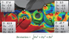
The three-dimensional differences between a intraoral scanning (reference) and conventional impression (test) were illustrated in a color-coded map. The comparison between full-arch (reference) and dual-arch (test) impression was also illustrated in a color-coded map. The green meant perfectly matching surface, the red meant test model surface was positively positioned relative to reference model and the blue meant test model surface was negatively positioned relative to reference model. For three-dimensional quantitative analysis, 4 specified contact locations (buccal and lingual cusps of second premolar and molar) were established (Fig. 1).

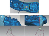
For two-dimensional quantitative analysis, the sectioning from buccal cusp to lingual cusp of second premolar and molar were acquired depending on the tooth axis. Buccolingual and apical direction of divergences were calculated (Fig. 2).
For identifying distortion after scanning, the ratio between width and length of constructed plane surface was compared to actual ratio. The width and length of regular size scanbody were 2.7 and 3.0 mm and those of wide size scanbody were 3.0 and 3.0 mm. Impression healing abutment, the width and length of section were 3.30, 2.87 mm (diameter 4.5 mm) and 3.37, 4.21 mm (diameter 5.5 mm) for each.
A statistical analysis was performed with SPSS software (SPSS statistics 21.0, SPSS Inc., Chicago, IL, USA) with 95% confidence interval to investigate the volumetric deviations from comparisons. For analyzing two- and three-dimensional deviations, one-way ANOVA was done. Scheffe's test for post hoc comparison was conducted.
RESULTS
Most of the superimposed surfaces were green, which indicates that reference model and test model were corresponded with each other. The difference between intraoral scanning and dual-arch impression were indicates by the most reddish and bluish one, showing. The biggest differences between reference and test model.
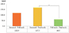
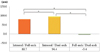
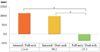
The biggest difference was seen between intraoral scanning and dual-arch impression. The smallest difference was seen between dual-arch and full-arch impression. The deviation between intraoral scanning and dual-arch impression at the buccal cusp of second premolar was 167 µm that was significantly bigger than the deviation between full-arch and dual-arch impressions (Fig. 3, Table 1, Table 2). Three-dimensional deviation at the lingual cusp of second premolar, buccal cusp of second molar (Fig. 4), and lingual cusp of second molar showed similar results to that of the second premolar buccal cusp. At the second molar buccal and lingual cusp, there were significant differences in all three pairs (intraoral/dual-arch, intraoral/full-arch, full-arch/dual-arch). There were significant differences according to the impression technique or contact locations.
At the buccal surface of second premolar, dual-arch digital model was positioned more buccally than intraoral scanning digital model (Fig. 5). It means restorations from dual-arch impression were more buccally located than intraoral scanning. At the occlusal surface, intraoral scanning digital model was positioned more apically than full-arch and dual-arch digital models. It means restorations from the intraoral scanning were more apically positioned than conventional impression techniques.
At the buccal surface of second molar, full-arch and dual-arch digital model was located more buccally than intraoral scanning and dual-arch digital model was positioned more buccally than full-arch impressions. At the occlusal surface, intraoral scanning digital model was placed more apically than full-arch and dual-arch digital models (Table 3, Table 4).
Full-arch and dual-arch digital model showed more error than intraoral scanning. Impression healing abutments showed much more errors than scanbody (Table 5).
DISCUSSION
The purpose of this study was to compare digital impression techniques and conventional impressions from the viewpoint of the tooth position. Although there were several in vitro studies comparing digital impression and conventional impressions for accurate assessments, there have been few studies performing clinical approach in vivo. In vitro study could not verify the exact discrepancies caused by jaw opening, saliva, blood and other factors in clinical situations.1724 Furthermore, most in vivo studies concentrated on the marginal fit or patient's comfort for the prosthesis using the digital impression.21 For an analysis of the scanning device, direct comparison of the data produced by the scanning devices rather than indirect assessment of the final prosthesis was proposed.25 Therefore, direct comparisons of the data were performed in this study.
As a reference model, digital impression using TRIOS® was performed. It is a powder-free device for the scanning process. Some intraoral scanners should apply the powder layer to the glossy, lucent tooth surfaces in order to avoid reflections and to create a measurable surface.2627 The powder layer applied to the scanbody results in an additional thickness. The powder should be applied only to the scanbody. However, it was impossible without layering adjacent teeth. A layer of powder spray on the tooth surface, and the inhomogeneous powder thickness may slightly transfigure the tooth outline.25 Even if the programs inside the scanners were capable of taking the powder spraying into account in the algorithm, the powder thickness was still varied by the operator, reducing scan accuracy. However, 3D laser scanner for indirect digital impression had to apply magnesium oxide powder to the glossy scanbody surface. Therefore, the possibility of data difference between digital impression and conventional impressions could not be excluded.
Conventional impression techniques were used to fabricate definitive casts for indirect digital impression. The potential laboratory errors such as shrinkage, irregular thickness or detachment of impression material and distortion of the impression were inevitable. Additional problems were dimension changes caused by the expansion of the dental stone.28 Current literature reported that a mean deviation of about 10 µm occurs when taking impressions and fabricating a cast.2930 It was considered as a negligible range to make an accurate restoration.
On the other hand, intraoral scanning had technology-related errors. Intraoral scanners lack fixed references.31 Thus, what it uses as a reference is the first image made by the scanner. All subsequent images are "stitched" to the previous one by a best-fit algorithm that represents the best possible overlap of images. Each overlap has an inherent error; as a consequence, the final error should be gradually increased with every stitching process. Hence, it can be anticipated that the longer the scanning field, and the more stitching processes completed, the larger the errors would be presented.32 Maximum differences, up to 170 µm were found in posterior area during complete arch scanning.24 Recent studies compare the accuracy of intraoral scanners.173132 Mean difference values of intraoral scanners might be varied by the scanner types, 49.0 µm for iTero and 332.9 for CEREC AC Bluecam. Another study reported mean positive and negative deviations was only 17/-13 µm in Lava C.O.S., however, maximal positive and negative deviations of and 134/-123 µm.17 The differences of deviations by the scanner type might be related to incorrect software stitching processes and a summation of matching error of the captured data during processing. The possibilities of deviations cannot be excluded in superimposition of the data. The deviations were affected by the choice of digitization method, reference scanner, best-fit alignment and distribution or number of surface data points.33
The scanning process of this study was executed by quadrant, beginning in the posterior areas, and images were connected to the anterior area. Three-dimensional deviations between intraoral scanning and dual-arch impression datasets were 167.5 and 153.9 µm for of a buccal and lingual cusp of premolar, while 94.4 and 89.2 µm for molar. The deviations of second premolar were bigger than second molar because the direction of scanning was from posterior to anterior. If the direction of the second scanning with intraoral scanner was from anterior to posterior teeth, the three-dimensional deviation of second premolar might be decreased. To maintain the amount of mouth opening during scanning process, the direction of scanning was from posterior to anterior. In addition, larger surface area of molar would be an appropriate reference which is the first image made by the scanner.
Present study compared the gypsum models from conventional impressions and datasets from intraoral scanning. The selection of tray (dual-arch or full-arch) was also included as the independent variable. The biggest difference was seen between intraoral scanning and dual-arch impression. The smallest difference was presented in the difference of dual-arch and full-arch impressions (Table 1). As previously described, conventional impression and indirect digitization was well controlled and provided a reliable accuracy. The difference between intraoral scanning and dual-arch impression might be caused by the errors related with the intraoral scanning.
At the occlusal surface, intraoral scanning digital model was positioned more apically than full-arch and dual-arch digital models. It means the implant position would have relatively occlusal location, therefore, restorations made in the models from intraoral scanning would have a possibility of hypocclusion than conventional impression techniques. Occlusoapcial deviation between intraoral scanning and conventional impressions might be caused by different scandbody fit with the implant body (intraoral scanning) and laboratory analogue (indirect digitization). From the result of this study, the implant analogue in the models from conventional method was placed in relatively lower position. When implant analogue/impression coping assembly were positioned into the impression, the implant analogue tends to be pushed upward due to the elastic rebound of the impression materials. This result is corresponded with the Stimmelmayr et al.'s34 study that measured reproducibility of implant scan bodies. For calculating exact vertical deviations, features of the scanbody such as vertical length and constructed plane should be considered.
Most previous studies concentrated on the differences of dual-arch and full-arch impression with regard to the marginal fit or abutment dimension, while this study presented 3D deviations between dual-arch and full-arch impression. There was opposite tendency of premolar and molar. The premolar and molar displayed the opposite direction of deviation. The averaged two-dimensional deviations between full-arch and dual-arch impressions at the buccal surfaces were -35.5 µm for premolar and 21.9 µm for molar. The negative deviation means the dual-arch digital model was lingually positioned than full-arch digital model. And the positive deviation means the dual-arch digital model was buccally positioned than full-arch digital model.
This study evaluated the deviations in superimposed impressions and could not distinguish superiority of each impression technique. It was not possible measuring the absolute accuracy of each digital impression techniques due to absence of reference model as a standard. Nevertheless, 25 pairs of digital model exhibited obvious differences between direct digitization with intraoral scanner and indirect digitization with conventional impression. Considering insignificant errors of conventional impression, these differences seemed to be mainly caused by errors of intraoral scanner. In spite of the convenience of intraoral scanner, it accuracy should be further improved for general use.
CONCLUSION
For evaluating impression techniques, by analyzing the superimposition of three-dimensional digital model to compare the accuracy of conventional impression technique and intraoral scanning, following conclusions can be drawn.
The three-dimensional deviations between intraoral scanner and dual-arch impression was bigger than full-arch and dual-arch impression (P < .05).
The second premolar showed significantly bigger threedimensional deviations than the second molar in the threedimensional deviations (P > .05).
The two-dimensional deviations between conventional impressions were smaller than intraoral scanner and conventional impressions (P > .05).


 XML Download