

 PDF
PDF ePub
ePub Citation
 Print
Print


INTRODUCTION
In highly industrialized countries, the percentage of edentulous people over 65 years of age is projected to decrease considerably.1 However, the absolute number of people over 65 years is expected to double by the year 2030, and the actual number of those needing complete dental prosthesis therapy will remain almost constant over the years.1 The removable restorative need of the elderly population poses unique challenges. Elderly patients and especially first time removable denture wearers often have difficulties adapting to removable dental prostheses and have problems attaining comfortable and efficient dental prosthesis function.2 Therefore today, osseointegrated implants are routinely used to improve dental prosthesis support, stability, and retention, especially in the mandible.3 Recently, several studies reported on the functional improvement of implant supported dental prostheses mainly focusing on balls, bars, magnets and telescopic crowns as attachments.456 The results indicate that more or less all types are viable treatment options. However, there is room for improvement, e.g. with regard to the ease of integrating the attachment system into the oral situation.67
Retention forces of implant-supported attachments are of clinical importance to not only provide stability during function, but also allow the patient to predictably attach and detach the prosthesis.8 However, appropriate retention forces may also serve as a mechanical safety mechanism to prevent overloading of implants. An attachment system that easily disengages when excessive loads are applied may protect the transmission of potentially harmful forces to the implants and the critical bone-implant interface.
Most implant attachments provide varying degrees of resiliency in both vertical and horizontal directions. Magnetic attachments provide no vertical resiliency, while quite effectively decreasing horizontal stress transmission to abutments.9 Bar attachments seem to be as suitable as other attachments concerning implant survival rate, improvement of retention and maintenance.5101112 However, due to their complex fabrication, disadvantages of conventional bar attachments occur with intra-oral implant impressions13 and production of the continuous bar in dental laboratories. Elastic and plastic deformations while removing the casting material, thermal and chemical contraction of cast and impression material as well as laser or molding techniques result in dimensional differences between the oral and model situation.14 These differences potentially add up and result in an incorrect connector-implant position. Consequently, these errors cause stress onto the supporting implants and its superstructure.15
In the current study a bar attachment system (SFI-Bar, Cendres+Métaux, Biel, Switzerland) for chair-side application was evaluated. It consists of an adjustable tube bar with an adjustable gold matrix, two large ball-joints and two screw-retained implant adapters. The system provided stable retention for up to 14,600 cycles of attachment/release.16 According to the knowledge of the author no data of the long-term retention, microleakage and plastic bar deformation of this bar system are available, yet. Therefore, this study was designed to investigate the magnitude of retentive forces, microleakage and the plastic deformation of the bar.
The hypotheses tested were:
1. The SFI 2-implant bar system delivers long-term retention forces in a clinically suitable range.
2. The system exhibits a good plastic deformation resistance at a long-term loading.
3. Sealing agents used in this study prevent microleakage on the bar/ball-joint connection.
MATERIALS AND METHODS
In order to measure the retention forces and microleakage on an attachment system consistently and simultaneously, eight special specimen holders were constructed. Each specimen holder had two implant analogues (synOcta analogue, Straumann, Basel, Switzerland) fixed in a socket of POM (Polyoxymethylene) with a width of 26 mm from axis to axis. Onto the analogues the specified implant adapters (Cendres+Métaux) were fitted with the required torsion moment of 35 Ncm using the original torque wrench of the manufacturer.
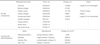
Three different materials were used to seal the joining areas at the end of the tube bars and the connector pin of the ball joints. One provided adhesive bonding to metals, the other two were bacteriostatic non-adhesive gels. The sealing materials used were an adhesive resin (AGC Cem, (AGC), Wieland, Pforzheim, Germany), a bacteriostatic silicon-based gel (GapSeal, (GS), Hager & Werken, Duisburg, Germany), and antimicrobial varnish (Cervitec plus (CP), Ivoclar-Vivadent, Schaan, Liechtenstein). They were applied in four different test groups with eight specimens each (Table 1):
1. Both sides were sealed with GapSeal (GS),
2. One side was sealed with AGC Cem and the other side with GapSeal (AGC+GS),
3. Both sides were sealed with AGC Cem (AGC),
4. Both sides were sealed with Cervitec plus (CP).
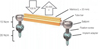
To provide as stress-free mounting as possible, one side of the tube bar was sealed and then assembled with a ball-joint followed by screwing it loosely into the implant adapter. Then the residual inner cavity of the bar tube was filled with 10 µL of a liquid red dye (Diffusions Rot Typ: BDR-L, Klumpf, Herten, Germany) using a micropipette with a small diameter tip. Finally, the second side of the bar tube was sealed with the related material, the second ball joint was plugged in and the complete structure was fixed on both sides on the implant adapters using the fixation screws with 15 Ncm torque (Fig. 1).
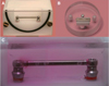
After mounting, the complete specimen was rinsed properly and immersed in clear water for one night to check for initial microleakage before loading. To detect the occurrence of microleakage during cyclic loading the attachments were immersed in a water chamber of 5 mL volume with free view on to it through an acrylic window in front of the specimen holder (Fig. 2).
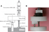
The asymmetrical female counterpart (E L30, Cendres+Métaux) was delivered shortened to a length of 20 mm. They were glued into a small block holder made from POM which simulated a removable dental prosthesis (RDP). The small block holder was screwed into a base plate at an eccentric radius of 12 mm. The base plate could be attached to mechanical actuators via a centric screw hole. A spacer limited the eccentric load to 0.2 mm below the point of full contact of the brace on the tube bar (Fig. 3).
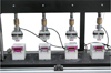
The experimental procedure was carried out in a programmable chewing simulator (Willytec, SD-Mechatronic, Feldkirchen-Westerham, Germany). The socket with installed SFI-Bar was fixed inside and the base plate with attached female counterpart was adapted to the moving stylus of the simulator. To assure assembling in parallel conjunction, the block holder with the female counterpart was set loose in the base plate. All parts were carefully arranged and fixed in the simulator with the system in attached situation. After that, the block holder was tightened (Fig. 2).
The simulator performed attaching and detaching cycles using a down and up movement of its crosshead with a cycle time of 2 seconds (Fig. 4). The styli were loaded with a weight of 10 kg which corresponds with the very slow down speeds roughly to a load of 100 N. The female counterpart was completely separated from the bar while detaching. To provide a balanced specimen loading only the four inner chambers of the eight test chambers were used. For each series 50,000 cycles were performed at ambient and water temperature at 20℃.
The retention forces were sampled via force sensors (U9B, HBM, Darmstadt, Germany) between the base plate and the styli. Simultaneous 4-channel signal recording were achieved using amplification (MGT 231, HBM, Germany), analog to digital conversion (DAQCard 6021e, National Instruments, Munich, Germany) and recording software (NI Diadem, National Instruments, Munich, Germany).
After completion of the loading cycles, continuously recorded timelines of the force signals were saved and the mean force and standard deviation over the first and the last 10 cycles was calculated for each test group (Fig. 5). One-way analysis of variance (ANOVA) was used to analyze the data with α≤0.05 level of significance using SPSS 15 software (SPSS GmbH, Munich, Germany).
In order to detect any plastic deformation caused by long-term loading, the deflection of the tube bars of three randomly selected specimens of three test groups was measured before and after cyclic loading in a confocal laser scanning microscope (µ-scan, Nanofocus, Oberhausen, Germany) with a vertical accuracy of 1 µm. In the measured 3D height map the topmost line between the beginning and the end of the tube bar was identified and exported as a 2D profile. The profiles for each selected specimen before and after loading were matched and the maximum deflection in the middle of the bar including surface roughness were calculated (Fig. 5).
RESULTS
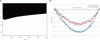
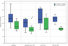
All four experimental groups showed a decrease in retention forces when comparing the first to the last ten cycles (Fig. 6). Means of the retention force for the initial ten cycles were 29.6 ± 8.2 N (GS+AGC), 36.1 ± 5.1 N (CP), 38.4 ± 11.3 N (GS) and 38.8 ± 12.6 N (AGC). At the final ten cycles the retention force decreased to 22.2 ± 7.1 N (GS+AGC), 21.6 ± 2.1 N (C), 26.9 ± 6.9 N (GS) and 27.6 ± 10.6 N (AGC). The mean losses of retention force were 7.4 ± 6.0 N (GS+AGC), 11.2 ± 6.0 N (AGC), 11.6 ± 9.9 N (GS) and 14.5 ± 5.8 N (CP).
When comparing the mean retention forces between the groups no statistical differences could be found at the beginning (P=.224) and at the end of loading (P=.257). Also, the decrease of retention force due to loading did not differ between the groups (P=.288).
None of the sealing agents showed a sufficient sealing over the total period of loading cycles (Fig. 4). In Group GS microleakage was detected after less than 200 loading cycles. In Group GS+AGC microleakage occurred after less than 2,000 cycles. Group AGC provided the longest resistance to microleakage, with approximately 10,000 loading cycles until leakage. Group CP showed immediate microleakage after immersion in clear water.
All measured deformations of the tube bars were less than 10 µm at the widest point and surface roughness did not show a noticeable difference between the beginning and the end of loading cycles (Fig. 5). After completion of the loading cycles, a film of dark micro particles remained at the bottom of the water chamber, potentially caused by mechanical wear. To validate which part of the system was abraded, the particles were scanned with an elemental analysis (EDAX XM 30, Philips, Germany). They consisted mostly (> 80%) of material of the female counterpart.
DISCUSSION
The new SFI-Bar provides a chair-side solution for implant-supported dental prostheses.1718 The manufacturer advertises the possibility of the system to be mounted completely stress-free onto the supporting implants. However, a finite element study using a load of 500 N concluded that the greatest amount of stress were concentrated on the connecting elements of the bar and the bar itself.15 A slight increase in stress can be observed with decreasing interimplant distance.15 With a non-zero fitting inaccuracy, for this system, no clear correlation could be found between the amount of play and the stress distribution in the system.15 For a perfect fit, an obvious increase in stress was found in the implant and strain in the implant bed.15 Nevertheless, this computer simulation concluded that the SFI-Bar is a system suitable for clinical application.
Another criterion for the clinical use could be the chair-side usage.1718 The simple adoption procedure leads to a shorter application time than other systems. However, major disadvantage of this system is the extra space required, which may therefore thicken the dental prosthesis.7 An increase in the amount of dental prosthesis thickness did not have a negative impact on either self-perceived oral function or patient satisfaction.7
The recorded retention forces were in the same range as reported for conventional attachment systems.1920 The attaching resistance and dislodging forces of the unloaded parts are in an acceptable range between proper fixation and too much stress while attaching to the supporting structure. With assuming 5 times dislodging a day, the number of performed cycles simulated nearly 27 years of clinical application. When looking at the results from this study only, it could be concluded that with at least 20 N remaining dislodging forces the achieved retention should be clinically sufficient even after long-term use. However, this study did not evaluate the impact of the daily stress, e.g. chewing or bruxism. It can be assumed that these additional factors decrease the life span of a dental prosthesis significantly.
Another important clinical aspect is the angulations of the implants. Another study showed that implant-angulations had no significant influence on the retention forces and wear of this bar system.16 Furthermore, this study revealed the significant reduction of the final mean removal torques. Consequentially, it is likely that the most often clinical complication will be screw loosening.16 The authors stated that this observation might be less important if 1-year recall intervals are respected.16
None of the tested sealing materials provided long-term prevention of microleakage. However, the gaps of the SFI-Bar system are located far above the peri-implant tissues. Therefore, microleakage and resulting bacterial colonization might be much less critical as compared to microleakage at the implant abutment interfaces, which has been determined in various studies.21 Sealing of the implant cavity with a bacteriostatic gel like GapSeal has been shown to reduce bacterial colonization.22 Therefore, although not providing long-term sealing the use of a bacteriostatic gel might be helpful to reduce bacterial colonization of the inner cavity of the SFI-Bar system and simplifies clinical handling as compared to using an adhesive resin. However, the particle size of the used liquid dye corresponds much more to the size of pyrogene metabolites (submicrometer) than to the typical size of bacteria (1-5 µm) in the oral microflora. Therefore, the present data cannot prove whether bacterial penetration really occurs. Within the limitations of this study, the results suggest that the retention of the new SFI-Bar attachment system might be clinically sufficient even after long-term loading.
Although the use of a bacteriostatic gel as sealing material does not prevent microleakage it might reduce short-term bacterial colonization. In a 1-year recall interval the bar should be dismantled, disinfected and re-sealed.
 XML Download