

 PDF
PDF ePub
ePub Citation
 Print
Print


INTRODUCTION
The dental industry has a long history in the development of dental prostheses to recover a patient's tooth function.1 As a substitute for teeth, a dental prosthesis must show stable durability, aesthetic value, precise function, and convenient use, as well as biocompatibility in order to perform the desired function properly. In addition, these factors must be applied to a wide range of manufacturing methods used in the construction of dental prostheses.2
Metal ceramic is a very common material used worldwide, and it has been successfully used as the gold standard for long-term clinical use; it provides excellent results in stability, aesthetic value, and marginal adaptation.345
In recovery using a dental prosthesis, marginal adaptation is an important factor.3 An inappropriate margin could cause a minute gap between the abutment tooth and prosthesis, which may lead to a periodontal lesion, plaque accumulation, secondary caries, microleakage, inflammation after endodontic treatment, or periodontal disease.5678 In addition, according to previous research, a defective margin may cause a failure of the long-term preservation of the prosthesis, resulting in an increase in the failure rate.9
Conventional fabrication methods for a prosthesis is a series of processes that includes taking an impression of the patient's oral cavity, pouring stone, producing a wax pattern, and performing the investing, casting, and polishing. However, during this process, the risk of inaccuracy may increase due to the properties of the material used and the worker's ability. In addition, temporal labor and cost could increase as well.1345 Therefore, to address these problems, an automated CAD/CAM system was introduced to the dental field.15 The CAD/CAM system is a type of subtractive manufacturing that cuts the materials to the desired shape and size. It enables a larger quantity of production than traditional methods, is easy to use, and saves the time. Because of these advantages, the CAD/CAM system is widely used.5 However, Bornemann et al.10 showed that this system tends to reduce accuracy through the scanning process, software design, milling, and a number of other related processes. This results in too much consumption of raw material, and the waste of bur was increased. Accordingly, the additive manufacturing (AM) method, which supplements labor-intensive conventional manufacturing methods and subtractive manufacturing methods with high raw material consumption, is being considered a technology-intensive alternative in the field.
Multi-jet modeling, an additive manufacturing process used in the dental field, is the 3D printer, which is very advantageous in terms of manufacture speed and applicability with various materials compared with other 3D printings, as it has a number of jet nozzles.11
As a very professional 3D printer, a newly-launched additive manufacturing process "Micro-SLA" is characterized by high accuracy, and thanks to its minute ability in realization it is more appropriate for manufacturing the dental prosthesis than any other printers. Also, compared to the other 3D printings, it is cheaper and speedy printing (14 mm/hour on the basis of the vertical standard) is possible to shorten the time required.
As a disruptive technology, AM has the potential to revolutionize our lives, work, and international economy.12
Only a few companies are applying AM to dentistry, and, therefore, there are a limited number of studies done in this field. Identifying the limits and advantages of this manufacturing method is an important task in the prosthesis and dentistry fields.
Thus, the purpose of this study was to verify whether the marginal and internal gap of a prosthesis made according to the AM method is within the clinically allowable range by conducting a comparative evaluation of the conventional lost wax technique (CLWT), the subtractive manufacturing system with wax blank milling (WBM), and AM with multi jet modeling (MJM) and micro-stereolithography (Micro-SLA). The null hypothesis was that there is no difference in the marginal and internal gap among the 4 groups.
MATERIALS AND METHODS
An acrylic model (standard working model AG-3 ZPVK 13, 14, 16, Frasaco GmbH, Tettnang, Germany) with abutment teeth was used. Therefore, the maxillary right canine, first pre-molar, first molar were provided with a 360° 1.0 mm chamfer preparation.13 The incisal and occlusal reductions were 1.5-2.0 mm.
The maxillary right canine, first pre-molar, first molar were reproduced using duplication silicone (Deguform®, DeguDent GmbH, Hanau, Germany). In the reproduced area, the epoxy model (Master model) was reproduced by pouring the epoxy (Modralit® 3K, Dreve Dentamid GmbH, Unna, Germany). For the reproduced epoxy model, 10 plaster molds for each tooth were produced using duplication silicone, and, as a result, a total of 30 molds were produced. After filling the plaster molds with type IV stone (Dentona esthetic-base gold; Dentona AG, Dortmund, Germany), a total of 30 study models were produced.
The study models were scanned by a non-contact blue light scanner (Identica; Medit Co., Ltd., Seoul, Korea). Based on the scanned files, a metal framework was designed by Delcam Power SHAPE Pro® (Delcam Plc, Birmingham, UK) according to the manufacturer's instruction, with the following parameters (thickness): 30 µm for the cement film, 0.3 mm for the maxillary right canine, and 0.5 mm for the maxillary right first pre-molar and first molar. From this design, a standard template library (STL) file was created.
For the CLWT method, the lost wax technique was applied. After applying separating medium onto the study models and passing through the wax dipping process, each of the 10 abutment teeth, 30 in total, were produced with an even thickness of wax. For the WBM method, the 30 wax patterns were produced, based on the STL files, using the CAD/CAM system (DWX-50, Roland DG Corporation, Shizuoka, Japan) and milling the wax blank (DMAX Co., Ltd., Seoul, Korea). For the MJM method, the 30 resin patterns were produced using the MJM Printer (Projet-DP3000, 3D system, Rock Hill, SC, USA) and the STL files by jetting the light curing resin (Build Material VisiJet DP200, VisiJet, 3D system, Rock Hill, SC, USA) and wax (Support Material VisiJet S100, VisiJet, 3D system, Rock Hill, SC, USA) simultaneously through the inkjet print heads. The resin was hardened by UV light and laminated. Finally, for the Micro-SLA method, the 30 resin patterns were produced using a Micro-SLA printer (Projet®1200, 3D Systems, Rock Hill, SC, USA) and the STL files, by projecting the desired metal framework via the beam projector onto the liquid UV curable plastic (VisiJet® FTX Green material, 3D Systems, Rock Hill, SC, USA). Sequential layers at 30 µm layer thickness were added until the patterns were complete. The test piece was mounted on the UV curing station and photopolymerized for 10 minutes.
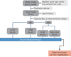
A total of 120 patterns were produced. The patterns were placed in the crucible former, covered with the metal ring, and invested in accordance with the proper water/powder ratio through phosphate-bonded investment (Deguvest-Impact-Degussa-Hüls, Hanau, Germany). After passing through the burnout furnace (Ring furnace, Seki Dental Co., Seoul, Korea), the nickel-chromium (Ni-Cr) alloy (VeraBond® 2V; AalbaDent Inc., Fairfield, CA, USA) was cast in the casting machine (Seki Dental Co., Seoul, Korea), and each test piece was produced (Fig. 1).
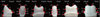
To measure the marginal and internal gap of the metal framework, skilled dental technician has used a silicone replica method. After mixing the light-body silicone (Aquasil Ultra XLV Regular Set, Dentsply Caulk, Milford, DE, USA), it was injected between the metal framework and model, and 50 N of finger pressure14151617 was applied. After hardening, the metal framework was separated carefully from the model, and heavy-body silicone (Aquasil Ultra Rigid Regular Set, Dentsply Caulk, Milford, DE, USA) was injected into the circular tray so that the light-body and heavy-body silicone could combine through an even pressure, and embed the light-body silicone. In order to cut the equal part, the zig (Modralit® 3K, Dreve Dentamid GmbH, Unna, Germany) was made by duplicating each two epoxy models, cutting one in a bucco-lingual direction, and cutting the other in a mesio-distal direction. The silicone replica reproduced by using this method was cut in a bucco-lingual direction and mesio-distal direction, respectively, using a razor blade (Fig. 2).
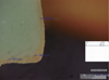
The thickness of the light-body silicone replica, which corresponds to the gap between model and the metal framework, was measured using a digital microscope (KH-7700; Hirox, Tokyo, Japan) at 140× magnification. The margin gaps (MGs), which corresponded to the absolute marginal discrepancy and internal gap, rounded chamfer (RC), axial wall (AW), incisal area (IA), and occlusal area (OA) were measured. To confirm an accurate measurement, the measurement points (16 in total) were checked on the zig and those points were measured (Fig. 3).
The total gap and the mean and standard deviation of the 16 points were determined, and this data met the hypothesis of a normal distribution (P>.01). The 16 points were divided into 4 regions as follows: MG, points 1, 8, 9, 16; RC, points 2, 7, 10, 15; AW, points 3, 6, 11, 14; and IA or OA, points 4, 5, 12, 13. After each region's mean and standard deviation were determined, two-way analysis of variance (ANOVA) was conducted to evaluate the difference in average values according to tooth type and fabrication method. As the reciprocal action between the tooth variable and fabrication method variable was significant (P<.05), this analysis allowed verification of the significance of the difference between groups as a full factorial model. Post-hoc test was performed using Tukey HSD. The level of the type I-error for statistical significance was fixed at 0.05, and the statistical analysis was conducted by using IBM SPSS Statistics 21.0 (IBM Co., Armonk, NY, USA).
RESULTS
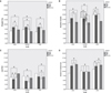
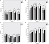
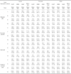
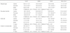
Results of the analysis of the marginal and internal gap according to tooth type and fabrication methods are listed as the mean and standard deviation (Table 1). The mean value of MG, RC, AW, IA or OA according to the four fabrication methods and the three tooth types are shown in Figures 4 and 5. As a result of the two-way ANOVA analysis of the means, there was a significant difference in MG according to tooth type (P<.001) and fabrication method (P<.037). In addition, there was a significant interaction (P<.001) between tooth type and fabrication method. Further, there were significant differences in RC, AW, and IA or OA according to tooth type (P<.001) and fabrication method (P<.001), with significant interaction (P<.001, Table 2) between tooth type and fabrication method.
The results of the post-hoc test using the Tukey HSD method (Table 2, Fig. 4, Fig. 5) indicate that MG was the lowest for the molar type fabricated using the CLWT method, and was the highest for the canine type fabricated using the MJM method. In the case of RC, the canine type manufactured using the CLWT method had the lowest value, while the molar type manufactured using the MJM method had the highest value. In AW, the premolar type fabricated using the WBM method showed had the lowest value, while the molar type fabricated using the CLWT method had the highest value. Lastly in the case of IA or OA, the canine type fabricated using the CLWT method had the lowest value, while the molar type fabricated using the MJM method had the highest value.
To assess the results measured at individual points (16 points), results were classified into four regions: MG, RC, AW, and IA or OA. In MG, the canine and molar types showed the lowest value when fabricated using the CLWT method, and the premolar type showed the lowest value using the Micro-SLA method. In the case of RC, the canine type showed the lowest value using the CLWT method, while premolar and molar types showed the lowest value using the Micro-SLA method. In case of AW, the lowest value of the canine type was shown using the CLWT method, while the lowest values for the premolar type and molar type were shown using the WBM method and the MJM method, respectively. In the case of IA or OA, the canine type showed the lowest value using the CLWT method, while the premolar and molar type showed the lowest value using the Micro-SLA method (Table 2, Fig. 4, Fig. 5). In addition, a whole AM, MG, IA or OA, and RC showed a lower value (Fig. 4, Fig. 5).
DISCUSSION
This study evaluated the marginal and internal gaps according to four fabrication methods, in order to verify the applicability of AM in dentistry. The internal gap showed a significant difference between the four fabrication methods. CLWT and Micro-SLA did not show a significant difference in the marginal gap, but, since these fabrication methods are significantly different from the other two methods, the null hypothesis was rejected.
As shown in Figures 4 and 5, the values increased in the following order: AW, MG, IA or OA, and RC. Because the abutment tooth was parallel to prosthetic appliance, AW showed a low value. However, because the occlusal surface has an irregular curve, IA or OA showed a relatively higher value compared to MG. RC had the highest value because the shape of the margin forms a rounded chamber.
According to the Table 2, the marginal gap using either CLWT or Micro-SLA was better than that using the other two methods. In other studies, CLWT has been shown to achieve the most suitable marginal-adaptation value, and, therefore, CLWT has been designated as the gold standard.5 However, considering that the Micro-SLA method shows no significant difference from the CLWT method in the marginal gap, we infer that the Micro-SLA method has a better fitness value than the WBM and MJM methods. In the WBM method, it is difficult to reproduce the projection part, undercut part, and sharp edge accurately due to the positive error, as well as negative error resulting from the limits of the currently available bur diameters.216 In spite of the advantages of the MJM method in delicacy and precision, it combines wax and thermoset material in the fabrication process. Thus, the MJM method has several drawbacks such as weak solidity among the 3D Printers and its deformation at high temperatures.12
As a modified method of digital light processing, the newly released Micro-SLA method projects a shaped light beam on the liquid photopolymer resin, hardens the resin as projected, builds the model layer by layer, and then, hardens the built shape by exposure to light again in the built-in UV curing station. The advantage of this method is that the manufacturing speed is even as the model forms and is comparatively fast. The Micro-SLA method shows high precision and surface roughness since the layers are applied at a thickness of 30 µm.
The SLS method and SLA method are currently the most widely used AM method.17
According to the research relating to the stereolithography (SLA) method, the mean (SD) of Margin, Axial wall, Occlusal are 96.9 µm (17.6 µm), 84.7 µm (16.8 µm), 114.2 µm (16.7 µm) respectively.17 And as a result of the research, MJM method and Micro-SLA method showed better fitness value, except the Occlusal part in the current study.
According to the report of Örtorp et al.,16 the mean (SD) value of the SLS showed the best fitness value, with the measured value 133 µm (89 µm), 117 µm (89 µm), 166 µm (135 µm), and 84 µm (60 µm), at all measurement points in the conventional lost wax method, milled wax method, milled Co-Cr, and SLS method. However, according to the earlier research, the mean (SD) value of the MG (absolute marginal discrepancy) part of premolar and molar made in the SLS method showed 132.1 µm (60.5 µm) and 128.0 µm (68.8 µm) each. And it was found that the SLS method has worse fitness than the MJM method and Micro-SLA method, showing the higher values than those of both methods used in the current study.15 Also, Kim et al.15 reported that the efforts to improve the SLS method will be required since the current SLS method is highly inferior to the conventional lost wax technique method and even has the gaps beyond the clinically allowable range.
According to previous studies, no difference is observed in the marginal and internal gap between anterior, premolar, and molar teeth.1819 However, Nakamura et al.20 showed that there are differences according to the tooth type. Our results on the canine, premolar, and molar teeth (Table 2, Fig. 4) indicate a difference in the marginal and internal gap according to tooth type. This is significant because each tooth type has a different morsal surface condition and appearance, although there is the uniformity in the tamper degree and chamfer margin. There are several ways to measure the fitness of a prosthesis, including a direct measurement after the cementation process of the prosthesis on the tooth model21 or observing the inside of the prosthesis using X-ray micro-computed tomography (micro CT).2223 In the present study, we used the cross-sectioning replica technique with silicone, which is considered the most suitable method to measure prosthesis prior to cementation.24
According to previous studies, there is much controversy as to the clinical validity of the size of the margin adaptation5. For example, Fransson et al.25 reported that the clinically allowable range is 100 µm, and the value suggested by McLean and von Fraunhofer26 and Belser et al.27 is 120 µm. Beuer et al.28 stated that the size of the marginal adaptation ranges from 100 to 150 µm and Boening et al.29 suggested the range is from 100 to 200 µm based on the long-term preserved prosthesis.
In this study, all of the MG results showed values within the clinically allowable range suggested by the preceding studies (Table 2). In addition, the values for RC, AW, IA or OA were also within the clinically allowable range (Table 1 and Table 2). Therefore, all the four methods can be used clinically.
A limitation to this study is that there could be an error in the resin pattern and wax pattern due to the characteristic contraction of the material itself. Thus, the development of suitable materials should be included in future studies, and, especially in the case of the AM methods, further clinical studies should be conducted.
CONCLUSION
All of the four fabrication methods have sufficient marginal adaptation, since the marginal and internal gaps were within the allowable clinical range. The results of the Micro-SLA method showed a statistically significant difference in outcome compared to the WBM and MJM methods and a significant difference from the gold standard CLWT method in the internal gap, but no statistically significant difference in the marginal gap from the CLWT method. Together, our results demonstrate that additive manufacturing can be used clinically as an alternative to the conventional lost wax-technique or subtractive manufacturing in the creation of dental prostheses.
 XML Download