

 PDF
PDF ePub
ePub Citation
 Print
Print


INTRODUCTION
Fixed implant-supported prostheses for edentulous mandibles are proved the best way to overcome the problems of traditional dentures, which enable patients to get similar bite force and comfort as natural teeth.1 However, a variety of prosthetic designs associated with implant fixed prostheses can be observed. The treatment protocol often adopted and favored by dentists is to place six parallel implants anterior to the bilateral mental foramen that are connected to one intact piece by a fixed bridge.2 Several retrospective studies have demonstrated that by changing the design of the fixed restoration, the implant number can be reduced to four, and the completed mandibular fixed prosthesis can achieve the same success rate as a fixed bridge containing six implants.345 For edentulous patients, four-implant-supported fixed protocol not only can simplify the operation and reduce trauma, but also can save one-third of the cost, which is desirable for elderly patients. This specific treatment modality is called "All-on-Four",6 featured by two anterior implants parallel and two terminal implants tilting distally, and a 10-tooth or 12-tooth prosthesis is built on the full-ach framework.
In the All-on-Four protocol, four implants are intraforaminally located and cantilevers are used. The cantilever extension is primarily determined by doctor's experience and patient's oral condition.7 Santiago suggested that the minimum number of implants was four and the cantilever length of 10 mm was the safest.8 Chiara9 found that if four implants were placed anterior to the mental foramen, a complete restoration of 14 teeth led to significantly increased stress levels on each implant, compared with the restoration of 12 teeth. This finding was primarily associated with longer cantilevers (15 mm). In theory, the safety to restore the full 14 teeth mainly depended on the length of cantilever, which could be kept in safe ranges by changing the position tilting angle and the length of the terminal implants. Experiments showed that it was possible to restore missing teeth to two teeth distal to the terminal implants,2 which was safe as long as the ratio of cantilever length to the distance between the anterior and terminal implants was equal or less than 2.10 To reduce the cantilever length, the terminal implants were usually tilted by a certain degree distally, which might be 17°, 30°, 34°, or 45°, and different tilting angles had different effects on the stress distribution.91112 However, another factor that may also influence the cantilever length has been neglected, that is the implant length. Experiments show that if the length of implant is reduced by 1/3, then the maximum length of cantilever should be shortened by 1/2.13 If the tilting angle of terminal implants is set, to ensure the implant shoulder stays at the level of alveolar crest, the practitioner must either maintain the apex of terminal implants unchanged and extend the implant length, or maintain the implant length unchanged and move the apex upward. The two methods can bring differences in the lengths of cantilevers which can exercise influence on stress distributions of the implants, periimplant bone, and framework. Whether there are some matching relations between the length and the tilting angle of the terminal implants has not yet been noticed in the literature.
In present study, the terminal implants were placed in the second premolar, three-dimensional (3D) finite element analysis was used to explore the effects of different tilt angles (0°, 30° and 45°) and different lengths (S for standard length and L for long length) of the terminal implants on the stress distributions of implants, bone, and superstructure when a full arch fixed prosthesis was used to restore the complete set of 14 teeth in edentulous mandibles.
MATERIALS AND METHODS
Primary mandibular impression of an edentulous patient was obtained, and an individual tray was made. Then, final impression was obtained with polyether impression material. Two plaster casts were poured sequentially, which were randomly named Cast A and Cast B. In Cast A, a lower full resin denture without buccal and lingual base was completed and this had a complete set of 14 mandibular artificial teeth, set up based on the dental arch morphology, requiring the second molar to be at least 2 mm anterior to the retromolar pad. When the denture was fitted back into Cast B, it fitted closely with the cast.
The lower full denture and cast B were scanned with a CT scanner (Toshiba Aquilion one-volume CT, with a slice thickness of 0.5 mm) to obtain DICOM data. The data were imported into the ITK-SNAP 3D medical image processing software (version 2.2.0). Based on the pixel gray value, the images were divided into two different regions: the mandible and the prosthetic upper framework. After triangular surface mesh reconstruction, the files were exported. Then, the mesh model files were imported into HyperMesh version 10.0 to establish the implant-surface mesh model, according to the experimental design. The material properties used in the finite element analysis were provided in Table 1. The tetrahedral element (Solid45) was used for the finite element meshing.
For the four implants to be embedded completely in the bone, implants (3.5 mm diameter and 10 mm long) were employed with the shoulder located at the same level as the alveolar crest. To simplify the model, the abutment and implant were set as an integral component and were ascribed the same parameters. The abutment was a cone with the diameter of upper surface and lower surface was 2.16 mm and 3.5 mm respectively, and the height was 3.5 mm. The bone-implant interface was assumed to be 100% osseointegrated. The framework was ascribed the gold-palladium alloy parameters,8 with the assumption that it had a complete and passive fit on the implants. The tetrahedral finite element mesh model files of the bone, framework, and implants were imported into ANSYS 9.0 and given boundary conditions. The mandible, framework, and implants were assumed to be continuous, homogeneous, isotropic, and linear elastic materials.91415 A 240-N load was applied to the mesiobuccal cusp of the right second molar in a direction perpendicular to the lingual slope (approximately 30° to the occlusal plane).8
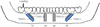
Four implants were employed and five 3D model groups were established. The two anterior implants (10 mm long) were parallel placed at the bilateral lateral incisor. The five groups were established based on the distal tilt angle and the length of terminal implants with its apex kept on the long axis of the second premolar. For Tilt0-S group, the terminal implants were parallel to the anterior implants and were of equal length. For the other four groups, terminal implants were tilted distally by 30° and 45° relative to the long axis of anterior implants. To ensure the implant shoulder was at the level of the alveolar crest and the apex was on the long axis of the second premolar, two-different-length implants were used to match each tilt angle. One was the same as the anterior implants, 10 mm, and the implant apex was approximately 9 mm (tilt of 30°) or 7 mm (tilt of 45°) distance from the alveolar crest. In the other condition, the implant apex was 10 mm distance from the alveolar crest, and the implant length was 12 mm (tilted 30°) or 14 mm (tilted 45°). Accordingly, relative to the same loading point, the cantilever varied. The schematic diagram of model design and implant ID were displayed in Fig. 1. The left side was the loading side, and from left to right, the implants were consecutively named #1, #2, #3, and #4. Table 2 presented the parameter values of the five implant configuration models.
RESULTS
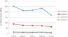
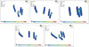
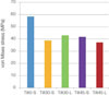
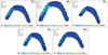
The stress distributions on implants of the five configurations were presented in Fig. 2. The #1 implant in all of the model groups showed the greatest level of stress, followed by the order of #2 > #3 > #4. The stress value of the #1 implant was approximately 3 times greater than that of #2 and 11-20 times greater than that of #3 and #4, and was concentrated near the neck (Fig. 3). Compared with Tilt0-S, the Tilt30-S group and Tilt30-L group exhibited similar patterns of stress variation on the four implants, with the stress value of the #1 implant reduced by 15.9% respectively; that of the #2 implant reduced by 13.6% and 16.1%, respectively; that of the #3 implant reduced by 21.8% and 26.4%, respectively; that of the #4 implant, in the Tilt30-S group displayed no significant changes, in the Tilt30-L group reduced by 10.3%. However, the stress changes on the implants were significantly different between the Tilt45-S group and Tilt45-L group. Compared with the Tilt0-S, the maximum stress levels of the #1 implant in the Tilt45-S and the Tilt45-L were reduced by 7.6% and 32.6%, respectively; those of the #2 implants were reduced by 18.5% and 28.8%, respectively; those of the #3 implants showed the greatest reduction of 26.4% and 33%, respectively; those of the #4 implant, in the Tilt45-S increased by 2.8%, in the Tilt45-L reduced by 27.9%.
The stress contours in Fig. 4 revealed that the maximum von Mises stress of implant-bone interface were all located around the distal neck of the #1 implants on the loading side. The stress levels were in the descending order of Tilt0-S > Tilt30-L > Tilt45-S > Tilt30-S > Tilt45-L (Fig. 5). Compared with Tilt0-S, the stress levels of the rest groups were reduced by 26.3%, 28.7%, 33.5%, and 36.3%, respectively.
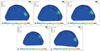
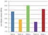
Fig. 6 indicated that the maximum stress distribution of the upper framework was entirely located in the distal cantilevers of the #1 implants. Compared with the Tilt0-S, the stress levels of the Tilt30-L and the Tilt45-L (have extended posterior implants) were increased by 6.5% and 2.6%, respectively; By contrast, the stress levels of the Tilt30-S and the Tilt45-S, in which the posterior implants were the same long as the anterior implants, were reduced by 8.4% and 11.0%, respectively (Fig. 7).
DISCUSSION
In order to extend the fixed implant-supported restoration success rate, four sites of the prosthesis need more attention for their stress level: the implant-bone interface,16 the implant-abutment connection, the abutment-framework connection, and the upper framework. Excessive stress on any of the four sites will cause frequent repairs, even failure of the prosthesis. To date, most of the research has focused on the implant-bone interface.9121517 Excessive stress on this site would cause absorption of the peri-implant bone, leading to implant loss. Excessive stress on the implantabutment connection would cause abutment screw loosening or fracture.1819 If excessively high stress was concentrated at the connection between the abutment and the upper framework, the results would be a loosened prosthesis or a loosened or fractured screw that connected the abutment and the framework. Excessive stress on the framework (beyond the maximum yield stress of the material) would lead to the frame's break.202122 The incidence of all the biological, mechanical, and technical complications was more frequent in cantilever bridge than in single crown and splinted crowns.23 Therefore, a comprehensive analysis and evaluation of stress levels at these positions in different implant configurations could provide a meaningful reference for design optimization.
In the present study, under the same loading conditions, the #1 implant (which was closest to the loading point) in each group had the greatest stress. There were significant differences in the stress levels among the four implants in the same model. The maximum stress level of the #1 implant was approximately 2-3 times greater than that of the #2 implant and 11-20 times greater than the level of the #3 and #4 implants, suggesting that the differences in the stress received by the four implants were not related to implant configurations. In all five model groups, the maximum stress was located near the neck of the terminal implant on the loading side, which was consistent with previous findings.5 The position of the implant neck clinically corresponded to the implant-abutment connection and abutment-framework connection. This fact suggested that if All-on-Four scheme was employed, the terminal implant abutment screw, the occlusal retention screw (when screw used for retention), or the cement (when cement was used for retention) must withstand greater stress, which should be paid more attention when prosthetic scheme was determined. The inclination angle of terminal implant and the length of cantilever have significant effects on stress distributions in implant-supported fixed prostheses.152425 Fazi et al.11 found that the stress level of the implant, the bone, and the framework were related to the tilt angle, which was in the order of 34° tilt < 17° tilt < 0° tilt. The present study revealed that the inclination of terminal implant indeed resulted in the decrease of stress level of the implants on the loading side to various degrees. The Tilt45-L group (terminal implants with the largest length and tilt angle, meanwhile the shortest cantilever length), exhibited the greatest reduction in stress on the four implants. However, the Tilt45-S group, which had the largest tilting angle (greater than the Tilt0-S group, the Tilt30-S group and Tilt30-L group) but a little shorter cantilever (10 mm) than the Tilt30-S group (12 mm) and Tilt30-L group (11 mm), the #1 implant exhibited less stress reduction (7.6 %) compared with the Tilt30-S group and Tilt30-L group, whereas the stress on the #4 implant increased slightly. Therefore, the stress on implant was not reducing accordingly with the tilt angle increasing and the stress variation was not completely explained by the change of tilt angle or the cantilever length. The length of the terminal implant also affected the stress level on implants. Because the upper framework was an integral-arc symmetrical structure that connected all implants, the four implants exhibited mutual restraint in the presence of a unilateral force. In the Tilt45-L group, an isosceles right triangle embedded in the mandible was formed by the implant shoulder, the implant apex, and the intersection between the second premolar' long axis and the alveolar crest. In addition, the loading direction was at a 30° angle with occlusal plane. Whether this unique stress performance was related to the unique stress interaction caused by the 45° angle and the symmetrical arc framework was unclear and worthy of further study. Based on the stress influence on the implants of the five model groups, the Tilt45-L was the preferred configuration, followed by the Tilt30-S. The Tilt45-L group, in which terminal implant tilted distally by 45° and the length was extended to √ 2 times that of the anterior implant, caused a maximum reduction in the stress on all the four implants.
The preservation of vertical bone around the implant was considered the key to success for implant-supported restorations.16 Many factors can affect the stress distribution of the surrounding bone, including implant number and position, cantilever length, tilt angle of the terminal implants, the occlusal surface morphology of artificial teeth, and the mandibular morphology.9111526 Even loading direction can change the stress distribution.15 The stress variation in peri-implant bone after distal tilting of terminal implants remained controversial. Some studies suggested that although the inclination of the terminal implant might shorter the cantilever, the implant shoulder was closer to the loading point, and greater stress was delivered to the surrounding bone.122728 Roshanak12 demonstrated that configuration with the terminal implant tilted resulted in 9% increased stress at its surrounding bone. However, others reported that four-implant configurations with the terminal implant tilted distally can resulted in reduction in stress on the implants, the bone, and the prosthetic components. 112425 Kim et al.17 demonstrated that distal tilting of the posterior implant by 30° reduced the bone stress by 17%, whereas Bevilacqua et al.27 suggested that the stress levels in the cortical bone and the cancellous bone could be reduced by 52% and 47.6%, respectively. In addition to the tilt angle, the cantilever length could also affect the stress on the bone.15 Chiara9 compared the stress in two All-on-Four configurations that employed a 5 mm cantilever versus a 15 mm cantilever, and found that the maximum values of compressive stress and tensile stress in 15 mm cantilever group were significantly higher than 5 mm cantilever group. The results of the present study demonstrated that the stress at the terminal implant-bone interface exhibited various reductions after tilting distally. The Tilt30-L group, the Tilt45-S group, the Tilt30-S group, and the Tilt45-L group exhibited reductions of 26.3%, 28.7%, 33.5%, and 36.3%, respectively, compared with the Tilt0-S group. This pattern of changes was not fully consistent with the cantilever length (11 mm, 10 mm, 12 mm, and 7 mm, respectively) or the implant length (12 mm, 10 mm, 10 mm, and 14 mm, respectively) of the model groups listed in Table 2. Because oblique loading was applied to the occlusal surface of the framework, we speculated that the reduction in stress level would be related not only to the reduced cantilever but also to the direction of loading and the morphology of the upper framework; Moreover, a best-match relation might exist between the tilt angle and the length of the terminal implants. Of the five groups, we could clearly identify the Tilt45-L group exhibited the greatest reduction in bone stress, followed by the Tilt30-S group.
The stress in the upper framework was also different in the five implant configurations. Fazi et al.11 demonstrated that, after the terminal implants were distally tilted by 17° and 34°, the maximum stress in the framework was decreased by 11% and 18%, respectively. The results of the present study indicated that the length of the terminal implants might also have an effect on the stress in the framework. Compared with the Tilt0-S group, the framework stress levels of the Tilt30-S and Tilt45-S, which had four equal-length implants, were reduced by 8.4% and 11%, respectively, but in the Tilt30-L and Tilt45-L, which had extended terminal implants, it was slightly increased (by 6.5% and 2.6%, respectively). The maximum stress in the framework was located at the cantilever distal to the terminal implants, suggesting that the strength of framework at this position should be enhanced to prevent breakage.
Different from Chiara's opinion9, in the present study, all 14 mandibular teeth were restored, and the Tilt45-L was proved to be the best protocol. Because in the Tilt45-L, the terminal implants were moved posteriorly by one tooth, tilted distally by 45° and extended to 14 mm; thus, the cantilever was correspondingly reduced to 7 mm, which was similar to the cantilever length that Chiara used for the restoration of 12 teeth. It was theoretically reasonable to restore the complete set of 14 teeth without adding cantilever length by increasing the tilt angle and extending the implant length. Therefore, we believe that it was possible to restore all 14 teeth using the All-on-Four protocol by optimizing the design. Notably, we only conducted the simulation analysis with 3D finite element models, and a number of experimental conditions were simplified during the experiment. Additional, in-depth studies followed by clinical validation should be required for Tilt45-L protocol to be applied in clinic.
CONCLUSION
With four-implant-supported fixed restorations for edentulous mandibles, configurations with the terminal implants tilted distally and extended in varying degrees resulted in various reductions in the stresses on implants and surrounding bone. Matching of the tilt angle and the length of terminal implants might maximize the reduction. Under the present experimental conditions, the Tilt45-L group was the preferred configuration. By optimizing the design, it was possible to restore all 14 mandibular teeth. However, whether this protocol could be used in clinic remained to be determined.


 XML Download