

 PDF
PDF ePub
ePub Citation
 Print
Print


INTRODUCTION
Immediate loading of implants is a treatment that yields high success rates1 and offers multiple benefits for patients, including immediate function and esthetics. Furthermore, immediate provisional restoration guides the healing of gingival tissues with a proper emergence profile. However, the success of dental implants is related less to loading time than to micromotion induced by immediate loading.2 Micromotion during the healing phase may lead to fibrous encapsulation of implants.3 The critical threshold for the development of this complication lies between 50 and 150 µm.2,4,5 Therefore, a high degree of primary implant stability (a high insertion torque value) seems to be a prerequisite for successful immediate loading.1
The amount of force required to produce micromotion depends on several factors, including: bone quantity and quality; insertion torque; implant length, diameter, geometry, threads and surface; and surgical technique.6,7,8,9,10 To date, no studies have been published describing a system to protect immediately loaded implants from overloading. The aim of this study was to test various screws designed for this purpose. For this reason, various temporary abutment screws were developed to act as fuses. These screws could be a useful tool to increase the predictability of implants under immediate loading. Through this protective mechanism, it was possible to control one of the critical risks associated with immediate loading.
In this study, various screws were developed for use with immediately loaded implants that were designed to break when subjected to overload, thereby avoiding micromotion that interferes with the osseointegration of the implant. After fracture, retrieval of the screw was intended to be easy. The screws were required to withstand 20 Ncm of tightening torque.
MATERIALS AND METHODS
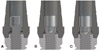
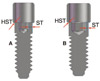
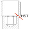
Seven types of Grade IV titanium screw fixing machined abutments to 112 external 3.75 × 13 mm hex implants (MG Osseous®; Mozo-Grau, S.A., Valladolid, Spain) were studied. The control screw was a titanium screw for definitive prostheses (Mozo-Grau, S.A.), whereas the other six were prototypes designed for this in-vitro study. The control screw comprised Grade IV titanium, with a hexagonal socket head cap measuring 1.25 mm in diameter (Fig. 1A). The prototype screws had hollow, smooth heads, with a hexagonal socket at the same level as the shank. Prototype 1 hexagonal socket was 0.9 mm in diameter (Fig. 1B and 2A), whereas Prototypes 2, 3, 4, 5 and 6 hexagonal socket were 1.25 mm in diameter (Fig. 1C and 2B). Prototypes 2, 3, 4, 5 and 6 differed in thickness at the level of the head shank union (Fig. 3). Table 1 shows the group allocation and dimensions of each prototype.
Implants were embedded perpendicularly into auto-curing resin cylinders 2 cm in diameter and 3 cm long (Paladur®; Heraeus Kulzer GmbH, Hanau, Germany). Afterwards, a machined titanium abutment was screwed to each implant using either a control screw or one of the six prototype screws. Using a torque wrench (Mozo-Grau, S.A.), 32 Ncm was applied to the control screws, whereas the prototype screws were subjected to 20 Ncm. Each of the seven groups was divided into two subgroups, with eight samples per group. One subgroup was under dynamic loading (the DL Subgroup), whereas the other was tested without prior dynamic loading (the NDL Subgroup).
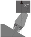
To perform an aging test, a semicircular, cobalt-chrome cast sleeve was cemented on the machined titanium abutment using permanent glass ionomer luting cement (Ketac™ Cem, 3M, ST. Paul, United States) to simulate cyclic load. Fifty-six samples (eight per screw type) were subjected to dynamic loading at 30° in a single-axis chewing simulator using 150,000 load cycles at 50 N and 50 Hz. All surviving samples in the DL Subgroup and all samples in the NDL Subgroup were tested for fracture strength in a universal testing machine (Quasar 5; Galdabini, Cardano al Campo, Italy). A cobalt-chrome cast sleeve with a flat face was cemented on the abutment using permanent glass ionomer luting cement. The cylinders with implants and abutments were fixed at an angle of 30° to the implant axis and direction of loading. The load center was situated 11 mm from the platform of the implant (Fig. 4). The load was applied in a progressive manner at a speed of 5 mm/min until the implant-abutment connection failed.
We verified that the values obtained, in terms of the resistance to fracture of each sample, followed a normal distribution (Kolmogorov-Smirnov test > 0.05). Afterwards, a mean was established for each sample, with a confidence interval of 95%. The Student's t-test was used to compare the data obtained on fracture resistance between samples submitted to cyclic loading and those not submitted to cyclic loading. Statistical comparison between groups was performed using one-way analysis of variance.
RESULTS
Under dynamic loading, only the eight samples in the Control Group resisted 150,000 cycles. Of the Prototype 1 screws, seven samples resisted dynamic loading. Of the Prototype 3 screws, five samples resisted dynamic loading, and of the Prototype 4 screws, six samples resisted dynamic loading. All samples of Prototypes 2, 5 and 6 failed during dynamic loading. The average numbers of cycles when the screws broke were 60,532 for Prototype 2, 54,658 for Prototype 5 and 4,198 for Prototype 6.
No statistically significant differences in fracture strength were found in control screws or Prototypes 3 and 4 before and after dynamic loading (P=.6306, P=.96 and P=.25, respectively). Of the screws in the DL Subgroup, Prototype 1 showed significantly lower resistance to dynamic loading (P=.0496; Table 2).
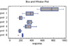
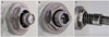
Statistical comparison of the seven screw groups and their fracture strengths without prior dynamic loading revealed significantly higher strengths (P<.05) in the Control Group compared with the six Prototype Groups. A comparison of the Prototype Groups is shown in Table 2 and Fig. 5. All samples in the Control and Prototype Groups broke in the same way, leaving 2 mm of the screw shank above the implant platform (Fig. 6A and Fig. 6B).
DISCUSSION
In this study, a screw was designed to fracture in a controlled way upon application of a force that could lead to critical micromotion. Fracture strength of the control and prototype screws were tested at 30° in two subgroups per screw: one under dynamic loading and the other without prior dynamic loading. Prototypes 2, 5 and 6 failed to resist 150,000 cycles of load. This finding is important and supports the use of Prototypes 2, 5 and 6. These observations are consistent with a recent study9 that underlined the importance of the magnitude, duration and frequency of micromotion as critical elements in the osseointegration process. However, because these screws were designed to fracture if necessary, their removal once fractured must be easy. Removing a fractured screw from inside an implant can sometimes be very difficult. The configuration of the prototypes with the hexagon located inside the handle and not in the head made it possible to position the screwdriver on the fractured screw (Fig. 6B). Therefore, a fractured piece of screw can be retrieved as easily as an undamaged screw (Fig. 6C). The function of the screw head was simply to keep implant and crown attached, not to hold the hexagon, associated with immediate loading. Taken all together, it can be concluded that three of the Prototypes used in this study - 2, 5 and 6- could serve as a fuse to protect immediately loaded implants from occlusal overload and micromotion.
The force necessary to produce critical micromotion in the osseointegrating implant depends on the individual circumstances of each case and implant. In addition, occlusal force values showed high variability between individuals and were predicated on the location of the implant in the mouth and the type of food eaten. Forces in the premolar area ranged between 300 and 450 N.11 The mean maximum bite force values for men were 909 N (standard deviation [SD], 177) in the molar region and 382 N (SD, 133) in the incisal region; significantly higher than the corresponding figures for women, at 777 N (SD, 168) in the molar region and 325 N (SD, 116) in the incisal region.12 For in-vitro analysis, Flanagan et al.13 conducted a study of the force required to produce specific micromotions, determining that 62 N at 45° (range, 48-86 N) and 87 N at 60° (range, 33-135 N) with a 4.3 × 13 mm implant in Type 1 mature bone were necessary to produce a micromotion of 100 µm. In a finite element analysis of how macro design affects the micromotion of implants under immediate loading,14 a 500 N force was applied at 70° from the horizontal plane to two types of implant 12 and 13 mm long and 4 and 3.8 mm in diameter, respectively. The micromovements measured were 284 µm and 148 µm, respectively. In a similar study using finite element analysis,6 a load of 300 N was applied axially to four different types of 3.3 × 8 mm implants; the micromovements measured were between 8.5 and 15 µm. In another in-vitro study of how insertion torque and bone density affect the micromotion of implants under immediate loading,8 30 N applied at 90° to a 4 × 13 mm implant placed in dense bone at 45 Ncm torque produced a micromovement of 41.72 µm ± 5.11. In this case, load application and measurement of implant micromotion were performed 10 mm above the implant neck. In a further in-vitro study of how the macro design of implants affects insertion torque and micromotion,15 the authors applied lateral loads of 10-100 N to three 4 × 13 mm implants of different designs in polyurethane foam blocks. They obtained average horizontal displacements of between 28 and 530 µm, 25 and 585.9 µm, and 42.6 and 782.3 µm. For in-vivo studies, obtaining the three-dimensional measurements in situ at the same time as applying a force is technically challenging, as reported by Engelke et al.16 in an in-vitro study that evaluated micromotion by means of contact endoscopy.
Taking into consideration the observed reference values and the growing number of published papers on the topic that have applied different methodologies, the complexity of the possible multivariate interactions becomes clear.15 Based on the results described here, it is suggested that Prototypes 2, 5 and 6 are suitable for use in vivo. Moreover, it was possible to place Prototypes 2, 5 and 6 using 20 Ncm of torque. However, this force may still be excessive for nonosseointegrated implants; therefore, the development of weaker prototypes remains necessary. It must be remembered that screws must support a sufficient preload to allow firm attachment of the implant to the prosthesis without risk of the screw loosening. If a weak screw is used, it will fracture at 20 Ncm torque. The behavior of prototype screws under dynamic loading was also investigated. The results indicated that the prototype screws are inadequate in terms of fatigue, in contrast to the control screws, which are designed to remain permanently in the mouth. The results obtained with control screws are similar to those obtained in a previous study,17 with no statistically significant differences between screws subjected to dynamic preloading and those not subjected to dynamic preloading.
Taking into account the limitations of this study, it is considered that Prototypes 2, 5 and 6 are useful tools for increasing the predictability of implants under immediate loading. Through this protective mechanism, it was possible to control one of the critical risks associated with immediate loading. Following on from this in-vitro study, we intend to test Prototypes 2, 5 and 6 in patients. The aim is then to evaluate the clinical efficiency of Prototypes 2, 5 and 6 using a larger sample size to increase the power of the analysis. We also believe that Prototypes 2, 5 and 6 can be used with partial or complete prostheses under immediate loading.


 XML Download