

 PDF
PDF ePub
ePub Citation
 Print
Print


INTRODUCTION
All-ceramic restorations have gained more popularity due to their high esthetic, high improvement in their fracture strength and good biocompatible properties. Recently, yttria-stabilized tetragonal zirconia polycrystals (Y-TZP) have been introduced to the dental professionals. These materials have to be fabricated in CAD/CAM (Computer-Aided Design/Computer-Aided Manufacturing) procedures that have been investigated under in vivo conditions.1 The partially stabilized zirconia shows high fracture strength and structural reliability compared to glass-ceramics when fabricated into prostheses framework. However, due to their low translucency of the light, all zirconia frameworks have to be veneered with glass-ceramics or porcelain for esthetic reasons. These veneering materials have to directly face with chewing force and moisture, resulting in cracks or chipping.2
Chipping of a veneering material is a typical failure of all types of ceramic covered dental prostheses. These chipping problems have been reported with porcelain fused to metal (PFM) restorations. However, the chipping problems with zirconia restorations are widely discussed at the moment. Various factors that might have an effect on chipping have been proposed, such as adhesion between framework and veneering, veneering thickness, and supporting morphology of the finish line.2
Nowadays, frameworks for all-ceramic crown design by CAD/CAM have been based upon empirical machine guidelines rather than clinical scientific data. Most of all CAD/CAM systems, the frameworks of the crowns are design to arbitrary thicknesses of 0.4 to 0.6 mm3. This is leading to non-uniform thicknesses of veneering porcelains.
Like porcelain fused to metal restorations, zirconia frameworks should be designed to provide the appropriate veneering porcelain thickness and support to minimize internal stress, reduce mechanical failures, and optimize esthetics of the veneering porcelains.4
The objective of this study is to compare the failure load and failure characteristics of two different zirconia framework designs of premolar crowns when subjected to static loading.
MATERIALS AND METHODS
Cobalt-Chromium casting master die was replicated from prepared preformed plastic maxillary right second premolar for all ceramic crowns. The preparation was prepared leaving a 0.8 mm deep chamfer finishing line; 1.5 mm of occlusal reduction; 6° occlusal convergence angle.
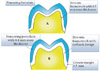
The master die was scanned using the inEos Blue scanner (Sirona, Long Island City, NY, USA). Scanned data were computed and then designed for all-ceramic crown framework using the CEREC 3D software (Sirona, Long Island City, NY, USA). Two different framework designs were made. First, the 0.5 mm thick framework (EV) including 0.5 mm thick crown margin was prepared (Fig. 1A). Second, cutback design was prepared as same as that of metalceramic crowns to obtain uniform, adequate thickness and support of 0.8 mm thick of the veneering porcelain (CB) with the same crown margin 0.5 mm. (Fig. 1B).
Subsequently, zirconia frameworks (10 frameworks/each group) were fabricated from pre-sintered zirconia ingot (InCoris ZI, Sirona, Long Island City, NY, USA) by a CEREC inLab MC XL machine (Sirona, Long Island City, NY, USA). After milling, the framework was removed from the machine and final sintering in an inFire HTC speed furnace (Sirona, Long Island City, NY, USA). The frameworks were examined and corrected if necessary, then cleaned with water steam. The framework was veneered with Vita VM®9 porcelain (ViDent, Brea, CA, USA) using brushing technique to derive the anatomical crown shape. The veneering porcelain was constructed under vacuum-former sheet to obtain the same total thickness of the crown. All crowns were calibrated by measuring at references point on buccal and lingual incline of the buccal cusp. Thickness of the restoration at the references point was 1.9 ± 0.1 mm. Several pilot specimens (4 specimens) were cut at the reference points to measure the real thickness of both zirconia framework and veneering ceramic. The thickness of veneering ceramic of the EV design crowns was 1.4 ± 0.06 mm whereas those of CB design crowns was 0.8 ± 0.05 mm, and those of zirconia frameworks were 0.5 ± 0.04 mm and 1.1 ± 0.07 mm respectively.
Before cementation, the internal walls of the crowns and the metal dies were cleaned with water steam. Each crown was cemented using resin cement (RelyX U-100, 3M ESPE, St. Paul, MN, USA) onto the metal die, using finger pressure then placed under a 2 kg load for 15 minutes.
All specimens were subjected to the universal testing machine (Instron Model 5566, Instron Corp, Norwood, MA, USA). The metal die was tilt out angle at 45 degree from the long axis. The cylinder rod with rounding head, radius 5 mm, was placed on the lingual incline plane of the buccal cusp of the crown. Therefore, the load was applied at 45 degree to the long axis of the crown at a crosshead speed of 0.5 mm/min until crown fracture occurred.
All specimens were examined under an optical light microscope (Nikon MM-11, Nikon Corp, Tokyo, Japan) and a scanning electron microscope (JSM-5410LV, JEOL Ltd., Tokyo, Japan). Three types of failure were defined.
The load to failure data was recorded in Newtons (N). The means and standard deviations were calculated. The difference between the even thickness framework design and cutback framework design of all ceramic crowns were examined using independent sample t-test at confidence interval of 95% (α=.05).
RESULTS
The mean and standard deviations of the failure load and failure characteristics of the crowns are shown in Table 1.
The mean and standard deviations of the EV design crowns was 1170.1 ± 90.9 N while those of CB design showed a bit higher at 1450.4 ± 175.7 N. The t-test showed the significant differences in the failure load among the tested groups (P<.05).
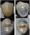
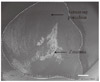
Under visual examination, the failure through the zirconia framework could be detected (Fig. 2), however cohesive or adhesive failure could not be classified by visual inspection. The scanning electron microscope was used to determine the failure modes (Fig. 3).
The results in Table 1 showed that all EV design crown found cohesive failure while the CB design crown found majority failure through the zirconia framework.
All of the crown fracture was found in splitting into a buccal and a lingual half pattern. The fracture lines ran from the position of the loading into the mesio-distal orientation towards the crown margin (Fig. 2).
DISCUSSION
The cutback framework design is based on what has been proposed previously for porcelain fused to metal restorations to overcome the porcelain chipping experienced at that times.5,6 Clinically, delamination and minor chip-off fractures of the veneering ceramic were found as the major reason for failures of zirconia fixed restoration.1,7,8 One of the reasons for porcelain fracture is improper framework design. The improper framework design causes the improper support for the porcelain veneer layer and also the nonappropriate thickness of the veneering layer. The modification of the framework design by creating an appropriate support and allowing the proper veneering thickness has been proved to reduce the porcelain chipping rates.4 Although there is no control group to compare the result, a clinical study on zirconia modified framework design on fixed partial dentures showed high survival rates in 3 years that can be speculated on the potential of the framework design for providing better porcelain support during function9.
In this study, a significant higher failure load was found for crowns with cutback design with optimal cusp support than the crowns with even thickness design. This result conformed to the previous studies that a framework with anatomical shape crown (cut back framework) withstood significantly higher loads before fracture than did crowns with even thickness framework.10 They explained the differences in fracture load by the thicker layer of veneering ceramic on crowns with even thickness framework. The larger the volume of ceramic, the larger the size of the flaw population and the higher the risk of prevalence of critical flaw.11,12
However, the failure characteristic in this study seems contradictory to the Bonfante et al.'s study.13 They predominantly found smaller veneer layer fracture on the crowns with cutback design framework than the crowns with even thickness framework. While in this study the cutback design framework crowns predominantly found failure through the zirconia framework whereas all the even thickness framework crowns found only veneer fracture. This may be due to the thick veneering ceramic (1.4 mm) with poor support is acting as the force defender of the crown, leading to veneering ceramic fracture before the loads are high enough to affect the framework. For cutback design crowns, the design creates an appropriate support and appropriate thickness of veneering ceramic (0.8 mm). Both creations lead to higher force withstand to affect both framework and veneer. The difference of both studies is the position of the load applied onto the crown. In this study, the force was applied on the buccal cusp with 45 degree to the long axis of the crown instead of the central fossa of the occlusal surface.
In this study, the force was applied 45 degrees to the long axis of the tooth because clinically, the shear force is the frequent force that occurred on this tooth. The alignment of this tooth is generally inclined buccally at an average 9.5 degrees to the occlusal plane.14 However, the chewing force is not occurred vertically but sliding contact motion. Theoretically, the maximum angle that can cause the highest force is 45 degree.15 As a consequence, it was assumed that this angle should cause the maximum load in the clinical application. The force was applied on the lingual incline plane of buccal cusp of premolar crown due to the clinical situation, the shear force occurs on this cusp. Maxillary premolar has been found that non-functional cusps of restored teeth have a fracture more frequently than functional cusps.16
According to the studies of Farah and Craig,17 Craig et al.,18 and Nally et al.,19 the stress distribution on the porcelain shows isochromatic shearing-stress trajectories radiating from the edges of the punch when loaded in compression. Therefore, Fracture in porcelain would start at these trajectories running mesio-distal orientation, leading to crown fracture found in splitting into half pattern in this study.
The employment of the single load to failure tests to understand the performance of dental materials has its limitations. In clinic, ceramic failure occurs from cumulative damage and slow crack growth20 when it is subjected to cyclic chewing force, approximately 380 N in the premolar area.21 This amount of force is much lesser than the failure force in this study. Thus, the results in this study need to be interpreted with caution.
In order to obtain more clinically relevant results, further research is necessary, including fatigue loading prior to static load tests for zirconia crowns.
CONCLUSION
Within the limitation of this study, the conclusions are as follows
Different framework designs have influence on the failure load and failure characteristics of all ceramic zirconia crowns.
The cutback zirconia design for all ceramic crowns is a promising way to reduce veneer chipping failures.

 XML Download