

 PDF
PDF ePub
ePub Citation
 Print
Print


INTRODUCTION
The precision of fit between the bearing surfaces of the implant abutment and component housed within a prosthesis framework has been questioned as being a significant factor in: stress transfer,1 biomechanics of load distribution,2 occurrence of complications,3 and response of the host tissues at the biological interface.4
Most authors agree that a passive fit between a prosthesis framework and implant fixtures is necessary to maintain the functional integrity of an implant prosthesis.5,6 According to Rangert et al.1, passive fit should exist at 10 micron level and is required to achieve an optimum load distribution. In previous studies, a correlation has been found between screw loosening and the marginal misfit of screw-retained fixed prosthesis.7-9 A clinical study on prostheses that were considered to have a clinically acceptable fit, which had measured mean center point misfits ranging from 91 to 111 µm, did not show a statistical correlation between degree of misfit and marginal bone loss.10-11
Cast implant bars are used for the fabrication of implant-supported and retained prostheses.12-17 An implant bar can be prefabricated or customized. The bar design that would allow for the optimum structural adequacy is a length of less than 18 mm with at least 2 mm of gingival extension (vertical stiffener).18 Conventional dental laboratory techniques do not allow the fabrication of a cast implant bar with an acceptable degree of accuracy of fit.19 The error is due mostly to the inconsistency of volumetric and linear expansion or shrinkage of the fabrication materials used, which include gypsum products, waxes (or pattern resin), investment, and casting metal. Potential distortion can be generated at any step of the fabrication process.15,20-23
Two options are available for correcting misfit of bars: the procedure can be repeated or the bar can be sectioned, indexed, and the bar segments joined using a connecting procedure. Different postcasting techniques such as soldering, additional casting, laser welding, Kal (Kulzer abutment luting) technique, and spark erosion have been developed to correct inaccuracies of fit resulting from the fabrication process.24-31 Laser welding offers a method which allows welding on the master cast or in the transfer record one procedure from the intraoral relationship.31 Additional casting technique has been used for a number of years in removable partial denture. Casting alloys to one another is an acceptable procedure in fabricating special components of removable partial denture frameworks. Weiss32 reported a similar technique for repairing base metal fixed partial dentures by casting the same alloy to a deficient substructure.
Despite the previous studies, little information or a selection guide regarding accuracy of correction methods for more passive fit of implant bar. Therefore, the purpose of this study was to evaluate the three-dimensional accuracy including horizontal, vertical and axial changes of soldering, laser welding, and additional casting techniques, allowed conventionally for correcting cast implant bars using contact coordinate measuring machine and a non-contact profile measuring machine. Three dimensional changes of gap, length and twisting after three correction methods were evaluated and was based on the measurement and comparison of (1) gap distances of the right abutment replica-gold cylinder interface (at buccal, distal, lingual side), (2) changes in bar length, and (3) axis angle changes of the right gold cylinders at the steps of before casting, after casting and after correction.
MATERIALS AND METHODS
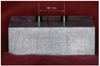
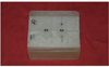
The master model was composed of two standard abutment replicas (Osstem, Seoul, Korea) permanently fixed into a tightly fitted hole. The abutment replicas were 18 mm apart and marked as left (L) and right (R) on the metal block (Fig. 1) using the same method used in our preliminary study.33 For the fabrication of implant bars, premachined gold cylinders (Osstem, Seoul, Korea) and round plastic bar patterns of 2 mm diameter were used. A custom transfer jig was used for this study because the standard deviation of the distances between two center positions should have been reduced. The transfer jig divided into two pieces bucco-lingually was applied to reduce the horizontal error, which occurs from the machining tolerance of a gold cylinder (Fig. 2). In our reported preliminary study,33 the tolerance of a gold cylinder in screwing arbitrarily was measured with the contact coordinate measuring machine. When the transfer jig was used, the mean distance between two center positions was 5.0 µm and the standard deviation was 1.1 µm. Significantly reduced mean distance and standard deviation was observed compared to those without transfer jig.
The premachined gold cylinders were screwed on the abutment replicas with gold screws (Osstem, Seoul, Korea), and the plastic bar pattern was positioned between the gold cylinders in the same location using a silicone matrix. The plastic bar patterns were luted to the gold cylinders with pattern resin material (Pattern Resin, GC America Inc., Chicago, IL, USA).
The specimens were sprued, and invested in a gypsum-bonded investment (Prestobalite, Whip Mix Corp., Louisville, KY, USA). Asbestos liner was laid out on the inner surface of the casting rings to obtain enough setting expansion in order to adequately compensate for alloy shrinkage in the casting process. All thirty bars were cast using type III gold alloy (Gold 78.0%, Platinum 1.0%, Silver 11.5%, Copper 8.5%, Others (< 1%): Ir, Zn) (Aurofluid®2PF, Metalor, Neuchatel, Switzerland) using 2-stage burnout cycle: first stage, up to 300℃ held for 30 minutes: second stage, up to 650℃ held for 90 minutes. Conventional lost wax technique, used with centrifugal casting machines, was performed. The specimens were allowed to bench cool to room temperature after casting. The bulk of investment was removed with an air chisel, followed by ultrasonic cleansing submerged in a hydrofluoric acid substitute solution. Air abrasion and polishing were not performed.
All bars were sectioned at 5 mm from the left gold cylinder with a thin separating disk of 0.3 mm thickness (ULTRA DISCS, Sejong, Seoul, Korea). Implant bars were placed and cut perpendicularly to the disk put into a fixed dental handpiece to obtain regular section thickness. The separating disks were changed every time. All laboratory works were made by the same operator, an experienced dental technician.
Group 1 (Soldering)
Sectioned specimens (1 to 10) were aligned with the transfer jig on the metal master model and tightened with gold screws. They were connected with the pattern resin. The bars were then left for 24 hours after being removed from the master model. All ten specimens were embedded in a high-heat investment at a depth of 10 mm and then placed into a preheating oven for 20 minutes at a temperature of 650℃. The invested specimens were removed from the preheating oven and placed on solder table. Borax flux (B flux, Ney Company, Bloomfield, USA) of liquid type was applied on both connecting edges of the bars to reduce surface tension and prevent oxidation. Solder (Standard S4 PF, Metalor, Neuchatel, Switzerland) was placed over the junction and melted with a gas-air torch to connect the bar segments. The same divesting and cleaning procedure as that used in casting was used. The specimens were allowed to bench cool to room temperature before divesting and cleaning.
Group 2 (additional casting)
After sectioning specimens (11 to 20), mechanical undercuts were created with the thin carborundum disk of 0.3 mm thickness at both connecting edges of each bar. The segments of the bars were aligned with the transfer jig on the metal master model and tightened with gold screws. They were then connected with the pattern resin, sprued at the junction using 10 gauge 10 mm long sprues, and invested in the same gypsum-bonded investment as in casting. Asbestos liner was also used. The burnout, casting temperature and gold alloy used were the same as those used to cast the bars. The specimens were allowed to bench cool to room temperature after casting.
Group 3 (Laser welding)
Sectioned specimens (21 to 30) were aligned and tightened on the metal master cast like group 1. A laser welding machine (Combilabor®, Heraeus Kulzer, Wehrheim, Germany) was used for correction of the bars in this group. Through a series of preliminary experiments, the machine settings that produced an effective weld were found. The machine settings were as follows: 1.00 mm spot size, 1.4 kw power, 6.0 ms duration, 1.0 Hz, 8.4 J energy.
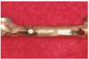
The specimens on the metal master cast were placed inside the laser unit on a working platform. Since laser welding technique requires flat approximating contact areas (of the parts to be welded) with as little space between the parts as possible, solder material (0.750 alloy, Heraeus Kulzer, Wehrheim, Germany) was inserted into the gap. Conventional laser welding resembling stitching had severely distorted a specimen in pilot study. So, laser welding technique should have been modified. Two-point laser welding vertically directed to buccal and lingual side fused the opposing edges undistortedly (Fig. 3).33-37 And then gasair torch soldering was performed on the laser-welded joint for reinforcing.
In this way, all 30 corrected cast implant bars were made.
For measuring bar lengths and axis angles of gold cylinders at precasting, postcasting and postcorrection steps, a contact coordinate measuring machine (contact CMM) (UPMC 850 Ultra, Carl Zeiss, Oberkochen, Germany) of moving-bridge type was used as shown in our previous study.34 It has a resolution of 0.08 µm and a reliability of ±0.2 µm for repeated measurements against a known datum by the manufacturers.
To measure gap distances at postcasting and postcorrection steps, a noncontact profile measuring machine (non-contact PMM) (Video-Check-L-400, Werth Messtechnik GmbH, Giessem, Germany) was applied. The CCD camera has a resolution of 0.4 µm and a reliability of ±0.02 µm for repeated measurements against a known datum. The integral segmented LED illumination and the 3D CCD camera allow an area of the measured component to be illuminated and viewed. All measurements were made by the same experienced operator.
Precasting measurement (Step 1)
At pattern state, precasting measurements were performed. Precasting measurements consisted of measuring bar lengths and axis angles of right gold cylinders.
The contact CMM was used to measure precasting bar lengths and axis angles of the right gold cylinders. When the bar length was measured, the probe tip touched and turned around on the inner surface of two gold cylinders of a bar to be measured, and then the distance between two center positions of the gold cylinders was calculated from the measured inner circles of two gold cylinders.
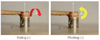
When the axis angle of a right gold cylinder was measured, the base of the metal master cast became a standard for measuring axis angle of the right gold cylinders and then the probe tip touched and turned around on outer circle or inner circle of the right gold cylinders, followed by calculating the axis angle of the right gold cylinder. Axis angle consists of rolling angle and pitching angle, and rolling and pitching movement turn on its X, Y axis, respectively (Fig. 4).
Postcasting measurement (Step 2)
Postcasting measurements consisted of measuring gap distances of the abutment replica-gold cylinder interface (at buccal, distal, lingual side), bar lengths, and axis angles of the right gold cylinders.
Postcasting gap distances were measured at the right abutment replica-gold cylinder interface with the noncontact PMM. The one-screw technique was applied to evaluate casting fit. After careful alignment of the specimens using the transfer jig, only the left abutment replica was torqued to 10 Ncm by a contra-angle torque driver (3i/Implant Innovations Europe, Copenhagen, Denmark) based on White's protocol24 using a new screw with the right abutment being left without a screw. Then gap distances were measured at buccal, distal, and lingual surface of the right abutment replica using the noncontact PMM. Four 'regions of interest' (ROI) were captured with the CCD camera at each side and followed by measuring and finding an average of the gap distances at magnified image (Fig. 5).
Postcorrection measurement (Step 3)
The data after correction procedure were collected on all three groups at the same locations and in the same manner as precasting and postcasting measurement.
The SPSS for Windows (Version 10.0.7) (SPSS Inc., Chicago, IL, USA) was used for statistical analysis. One-way analysis of variance (ANOVA) was performed to test for significant differences among the three groups (P<.05). Statistical significance between step 2 and step 3 within each group was evaluated using paired t-test (P<.05).
RESULTS
After the casting and correction procedure, the mean gap distances at buccal, distal, lingual side were observed in the Table 1. The data of gap distances were analyzed among the three groups by one-way ANOVA. Although there was no statistically significant difference among the three groups (P>.05), gas-air torch soldering technique produced the smallest gap distances and soldering and additional casting technique showed more consistent standard deviation. Laser welding technique was yielded the greatest gap distances and variable standard deviation. Gap distance between step 2 and step 3 was statistically evaluated by paired t-test within each group. The buccal and lingual gap in the soldering group and only lingual gap in the additional group reduced significantly by correction (P<.05).
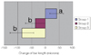
The mean bar length was 17994.8 µm for the group 1, 17924.2 µm for the group 2, and 17894.9 µm for the group 3 (Table 2). The measured distance between the abutment replica was 17970.1 µm. Therefore, Group 1 was the most closest to the distance between abutment replicas although there was no statistically significant difference among the three group. As bar lengths of step 1 were bases, the mean net changes of bar lengths from step 1 to step 3 were calculated and analyzed among three groups by one-way ANOVA, there was a statistically significant difference (P<.01). Based on Scheffe's post hoc tests, there was a significant difference between group 1 and group 2, 3 and no significant difference between group 2 and group 3 (Fig. 6).
From the pre-casting and the post-correction measurements, axis angles changes (axial error) of the right gold cylinders from step 1 to step 3 were calculated and analyzed among the three groups by one-way ANOVA, there was no statistically significant difference (P>.05). There was a tendency of positive axis angle change except in the pitching angle change of soldering group (Table 3).
DISCUSSION
The fabrication of an implant bar assembly involves a variety of clinical and laboratory steps, including impression taking, master cast fabrication, bar assembly wax-up, sprue and investment techniques, and finally casting and finishing procedures. The potential to generate a distortion exists at each of these steps, which may result in a non-passive fit of the restoration.35-38
Currently, conventional lost wax technique, used with centrifugal casting machines, is the most common method of implant prosthesis fabrication. However, the resultant mis-fitting castings often require corrective sectioning and soldering. The purpose of this study was to evaluate an accuracy of three different techniques for correction of non-passive fit. The techniques used in this study were soldering, laser welding, and additional casting technique. These correction methods are used in common for adjusting misfit error of casting implant bar. It was dealt with three dimensional accuracy of vertical, horizontal and axial view with precision coordinate measuring machine in this study.
In measuring gap distance, the technique with the most accurate and consistent results was gas-air torch soldering, although there was no statistically significant difference among three groups. It was supposed that distortion of the positions of the framework segments during gas-air torch soldering was less than that of other groups. Laser welding technique yielded the greatest gap distances and standard deviation. A study showed that post-joining distortion was significantly smaller in laser-welded castings than in soldering, and significantly reliable (least error variance) in joining with laser than either one-piece casting or soldering.39 Laser welding technique does not connect the segments of a bar simultaneously and it is not like other two techniques. More gap might be created unless a laser beam is vertical to the buccal and lingual surface.
In bar length measurement, all three groups showed a decreasing tendency after casting procedure (step 2) compared to pre-casting. Bar length of laser welding and additional casting group showed a decreasing tendency even after correction procedure (step 3) whereas soldering group showed an increasing trend. The solder investment provided more expansion than that to compensate for the solder metal shrinkage. The bar length of additional casting group using the same investment as that of casting procedure decreased after correction method. Expansion of the gypsum-bonded investment used for casting procedure in this study was relatively small. Selection of additional casting investment was supposed to be crucial for compensating metal shrinkage.
The objective to measure axis angles was to evaluate twisting tendency. In fact, axis angle is a 3-dimensional combination of gap distances at buccal, distal and lingual side of the right abutment replica. The tendency of total gap distances accorded with positive rolling and positive pitching angle change from step 1 to step 3. Gas-air torch soldering group showed the least change of rolling and pitching angle. However, 3-dimensional combination of gap distances at buccal, distal and lingual side was not equal to axis angle exactly in our study because the interface of components made by a milling machine was not a plane surface but a curved surface.
Even though the techniques used in this study strictly followed the guidelines established in the literature, the bars corrected by three techniques all yielded gap distances that were beyond acceptable accuracy. Inconsistencies in the linear and volumetric expansion of the materials used made such inaccuracy unavoidable. Laser welding technique showed relatively large variation and deviation in all measurements. So it seems technique-sensitive in correcting error of implant bar. Only under strictly controlled condition by an experience technician, it may be used as an alternative of conventional soldering technique for correcting implant frameworks.
CONCLUSION
Within the conditions and limitation of this study, there was no statistical difference according to correction methods in correcting vertical and horizontal errors. But, gas-air torch soldering technique showed the most accurate and consistent trends in horizontal, vertical and twisting (distortion) measurements. Laser welding method showed large amount and deviation in vertical and twisting changes in contrast to the others.


 XML Download