Abstract
PURPOSE
This study aimed to investigate the potential clinical application of digitized silicone rubber impressions by comparing the accuracy of zirconia 3-unit fixed partial dentures (FPDs) fabricated from 2 types of data (working model and impression) obtained from a laser scanner.
MATERIALS AND METHODS
Ten working models and impressions were prepared with epoxy resin and vinyl polysiloxane, respectively. Based on the data obtained from the laser scanner (D-700; 3Shape A/S, Copenhagen, Denmark), a total of 20 zirconia frameworks were prepared using a dental CAD/CAM system (DentalDesigner; 3shape A/S, Copenhagen, Denmark / Ener-mill, Dentaim, Seoul, Korea). The silicone replicas were sectioned into four pieces to evaluate the framework fit. The replicas were imaged using a digital microscope, and the fit of the reference points (P1, P2, P3, P4, P5, P6, and P7) were measured using the program in the device. Measured discrepancies were divided into 5 categories of gaps (MG, CG, AWG, AOTG, OG). Data were analyzed with Student's t-test (α=0.05), repeated measures ANOVA and two-way ANOVA (α=0.05).
The methods and technologies for preparing dental prostheses have experienced continuous dramatic developments. Especially after the 20th century, as computer-assisted processing was incorporated into dentistry, technologies for producing dental prostheses developed exponentially.1 Nonetheless, despite the advancements in manufacturing processes and technology, accurate image acquisition of the restoring position remains of paramount importance in fabricating dental prostheses.2 Scanners are vehicles for obtaining dental images in dental computer-aided design/computer-aided manufacturing (CAD/CAM) systems for constructing fixed dental prostheses. Depending on the dental CAD/CAM system, different processing routes may be applied to obtain data for dental restoration, as well as for various digitization methods to convert the planned restoring abutments to virtual abutments. In other words, a virtual three-dimensional (3D) model is created based on 3 sets of data (stone cast, impression body, and intraoral) acquired from the scanning process. Therefore, the complexity of the overall manufacturing process of a dental prosthesis may increase or decrease depending on the material of the scanned object. The most efficient manufacturing process in fabricating a dental prosthesis would ideally include only the necessary steps, but efficiency may not always enhance the fit of the final restoration. For example, intraoral scanning can eliminate 2 stages, impression obtainment and working model preparation, that are necesary in conventional dental prosthesis manufacturing processes.3,4 However, doing so may generally reduce the precision of the marginal and internal fit due to excessive coating of titanium dioxide during the scanning process.5,6 Cast scanning, a commonly used method, has the disadvantage of adding another step over those employed in impression scanning, as preparation of a working model is necessary. Hence, impression scanning is a method in reducing the manufacturing process, such as pour first dental stone into impression, fix pins in dental stone model, pour second dental stone as base, section die. A prior study analyzing the accuracy of scanned data from impression bodies and stone casts reported that eliminating the stone cast production stage can improve process efficiency.7
Therefore, identifying a fabrication method that can simplify the manufacturing process while maintaining high precision is clinically valuable. The purpose of this analysis was to assess the marginal and internal accuracy of zirconia 3-unit FPDs fabricated from 2 sets of data (working model and impression) obtained from a laser scanner to investigate the possibility of digitizing dental impressions utilizing dental laser scanners.
To create the 3-unit FPDs used in this study, a typodont plastic model with maxillary right second premolar tooth loss was made (Model #3017; Viade Products, Camarillo, CA, USA). An abutment with a 1.2 mm, 360 degree chamfer was prepared on the maxillary first premolar and maxillary first molar. A single impression (Fresh, Dreve Dentamid GmbH, Unna, Germany) was obtained via an individual impression tray (Trayplast, Vertex, Netherlands). The original model of the full mouth was completed by injecting epoxy into the inner side of the impression (Modralit® 3K, Dreve Dentamid GmbH, Unna, Germany). Areas of the original full mouth model that were irrelevant to the study were removed. Ten silicone molds (Dublisil, Dreve Dentamid GmbH, Unna, Germany) were obtained from the single original model that was ground. Epoxy was inserted into each of the silicone molds to prepare 10 working cast duplicates. Impressions were obtained from the working models. As a result, 10 sets of working models and impressions were prepared.
In the experiment, an optical scanner that uses laser as its light source was selected (D-700; 3Shape A/S, Copenhagen, Denmark). Following the user manual, the working model was placed inside the scanner, and a primary scan of the entire model and a secondary scan detailing the abutments were conducted. The impression bodies were also scanned under the same conditions as the working models. Finally, a 3D virtual model of the working models and impressions was generated.
Three-unit FPDs were designed from 2 types (working model and impression) of 3D virtual models using designated software tools (DentalDesigner; 3shape A/S, Copenhagen, Denmark). The framework's retainer thicknesses were 0.5 mm, and the cementing spaces were 30 µm. The designed framework was fabricated by milling the presintered zirconia block (Zirmax, Dentaim, Seoul, Korea). A total of 20 milled frameworks were sintered in an electric furnace (Eco-therm, Dentaim, Seoul, Korea) according to the provided instructions.
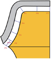
The inner sides of the completed retainers of the zirconia 3-unit FPDs were filled with light body silicone (Dimension Garant L; 3M ESPE, Seefeld, Germany). The cast of the framework was then placed on the abutment, and loading was applied using finger pressure from the occlusal surface to the cervical. The framework was carefully removed from the light body silicone, so the film would remain on the abutment. To prevent air bubbles from accumulating around the margins of the silicone replica, a highly flowable blue-colored light body silicone (Fresh, Dreve Dentamid GmbH, Unna, Germany) was added. Finally, a violet-colored heavy body silicone (Fresh, Dreve Dentamid GmbH, Unna, Germany) was used to fill the inner side of the customized tray, which was applied on top of an orange-colored silicone film, thus completing the preparation of the silicone replica (Fig. 1).
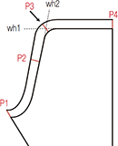
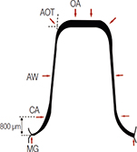
The first premolar and the first molar area were sectioned using a razor blade from the center point of the occlusal surface to the mesial-distal and the labial-lingual directions on the silicone replica. Using the quartered-silicone replica, the gap between the abutment and the retainer was measured. The marginal gap was measured at P1, and the internal gap was measured at P2, P3, P4, P5, P6, and P7 (Fig. 2). This study applied the definition of the marginal gap as cited in Holmes et al.8 The internal gap was measured by calculating the vertical distance of the orange-colored light body silicone.9 All gaps were evaluated under a digital microscope (KH-7700; Hirox, Tokyo, Japan) with 160×magnification.
Average measurements of gaps from mesial, distal, buccal, and lingual were used for P1 to P7. The measurements of P1 to P7 were summarized as mean and standard deviation and Student t-test was used to assess the significance of differences as the distributions were considered as normal (skewness < 0.5). Measured discrepancies were subsequently divided into 5 categories of gaps as follows: 1) marginal gap (MG), P1; 2) cervical gap (CG), P2; 3) axial wall gap (AWG), average of P3 and P4; 4) axio-occlusal transition gap (AOTG), P5; 5) occlusal gap (OG), average P6 and P7. The repeated measures analysis of variance (ANOVA) was used to assess whether there are differences between two frameworks, between two teeth types, and whether the interaction effect between frameworks and tooth types was significant, under consideration of 5 categories of gaps from the same tooth. As an assumption of sphericity was rejected (P<.001) and Greenhuse-Geisser epsilon was less than 0.75 (epsilon = 0.62), the Greenhuse-Geisser correction was applied. Especially for the marginal gap, the two-way ANOVA was performed to determine whether there are significant differences according to different frameworks and teeth types. A statistical package SPSS version 12.0 (SPSS Inc., Chicago, IL, USA) was used and a type one error rate 0.05 was applied in the statistical testing.
Overall mean discrepancies (standard deviation, SD) of the framework fabricated using the 3D scanned data of the working model and the 3D scanned data of the impression were 90.1 µm (13.8 µm) and 108.3 µm (14.5 µm) in premolars, and 117.6 µm (21.2 µm) and 144.4 µm (27.5 µm) in molars, respectively, which showed significant difference in premolars (P=.003) and molars (P=.002) (Table 1). While mean marginal gaps (SD) in the working model and impression were 54.1 µm (16.4 µm) and 68.8 µm (31.1 µm) in premolars, which showed insignificant difference (P=.208); in molars those were 74.5 µm (21.6 µm) and 117.7 µm (39.9 µm), respectively, which turned to be significant difference (P=.007)(Table 1).
As the results of the repeated measures ANOVA, significant differences were found among MG, AWG and OG (P<.001). Results of pair-wise comparison showed means of all 5 categories of gaps were significantly different (P<.05). AWG was the smallest as the estimated mean 41.4 µm; MG followed with estimated mean 78.8 µm; the third one was CG with estimated mean 107.0 µm; the forth one was OG with estimated mean 132.9 µm; and AOTG was the largest with estimated mean 271.2 µm (Table 2).
Difference between two framework fabrication methods were highly significant (P<.001); Gap of working model showed significantly smaller gap compare to impression in MG, CG, and AOTG. However differences between two framework fabrication methods were not significant in AWG and OG (Table 3).
Difference between two teeth types were statistically significant (P<.001); gaps in molar were larger than ones in premolars in MG, CG, and AOTG. However differences between two teeth types were not significant in AWG and OG. The interaction between two framework fabrication methods and two teeth types was not significant (Table 3).
The two-way ANOVA for marginal gap (R-squared 0.676) revealed significant framework fabrication method effect (P=.003) and teeth type effect (P=.001); Gaps in working model were smaller than those in impression by mean difference 28.9 µm and gaps in premolars were smaller than those in molars by mean difference 34.7 µm (Table 4).
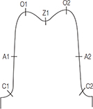
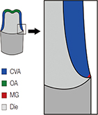
Most dental CAD/CAM systems are complete solutions, performing functions from scanning and designing to milling; however, it is important to consider the individual process in each stage as it affects the overall accuracy of the framework. Statistical data on accuracy can serve as an indicator for the quality of fixed dental prostheses. As a result, researchers have conducted various investigations for measuring and enhancing the accuracy of these structures. This study explored the possibility of clinical application of digitized impressions based on the accuracy assessment of the scanned data from 2 types of objects. Within the limitations of this study, the findings were similar to the results obtained in the literature on the accuracy of CAD/CAM system-generated 3-unit FPDs (Table 5).
Various definitions of marginal gap and measurement methods were suggested in the literature. There were also diverse methods of determining the locations to measure the internal gap. However, much of the research stopped short, measuring only the marginal gap or the absolute marginal discrepancy.10-15 Through this method of research, namely measuring the marginal gaps of limited locations, it is difficult to make an accurate assessment of the marginal and internal conditions, which in turn reduces the credibility of the research. Therefore, to enhance accuracy, the silicone replicas were quartered in this research, and the fit of the prostheses were measured from 7 different locations on the quartered replica. Furthermore, the abutments were prepared to replicate the die as closely as possible to increase the clinical validity. The silicone replicas used in this research adopted the techniques derived from the research of Kohorst et al.16 A majority of the background research studying the accuracy of the copings or frameworks selected this method to compare the results of their findings.17-22
To measure the discrepancy of each framework, measurements were taken from the reference points P1-P7. After obtaining the measurements, each of the discrepancies recorded from the reference points were divided into 5 categories. Analysis of the previous research revealed that the mean marginal gap in previous in vitro experiments was around 9-82 µm.23-27 In other research, the clinically acceptable range was defined as 120 µm or smaller.28 The marginal gap range in this study was 54.1-117.7 µm. Therefore, the marginal gaps of the 2 groups (working model and impression) were within the clinically accepted range; internal gap values were not much different with previous studies.12,25,29,30
The gap at CG was wider than that of AWG due to in part the fact that the curved shape of the margin of the abutment made it difficult to mill the area appropriately compared to that of the relatively straight line of the AWG.19,31,32 Moreover, the AWG showed the smallest value of discrepancy. This is plane part without curves and thus we can obtain more precise scan data than in the curve planes. Accordingly, the scan data which was moved by way of CAM software must have controlled the milling machine more precisely. Also, it seems that the burning shrinkage which appears in the sintering process appears more in the mesio-distal direction of the abutment being affected by the thick pontic and thus the value of discrepancy showed to be small. Also, it could be presumed that the contraction of impression materials affected the AWG. The widest gap was measured at the AOTG area, which had the widest gap in the 5 categories. It is reported that over-shooters appearing around the edges were due to the milling instruments used in dental CAD/CAM systems.33 The increased internal gap can be explained by discrepancies in the actual abutment. The gap value in the 5 categories increased in the order of the axial wall gap (AWG), marginal gap (MG), cervical gap (CG), occlusal gap (OG) and lastly axio-occlusal transition gap (AOTG). Overall, in all the categories, the framework fabricated from the scanned data from the impression had larger gaps than those of the cast model. To be more specific, the gap value of the 2 groups increased 30.5% in the premolar and 33.3% in the molar. The unusual gap dimension increase at the AOTG and OG of the framework from the impression scan compared to that of other categories could have been caused by the milling instruments; however, it could also be presumed that the limited resolution of the scanning system for the digitalization of the concavity, the diameter and length of the negative abutment formed in the impression and the color of the impression material affected the quality of the scanned impression data.7,34-36
It generally takes many stages to finish a dental prosthesis. This study fabricated 2 groups (working model and impression) of zirconia 3-unit FPDs utilizing the dental CAD/CAM system. The only difference between the 2 groups was the first stage, i.e., the method of obtaining the scanned data; the rest was identical. This study has configured the null hypothesis of 'two types of scandata are the same', measured the fitness of the framework and assessed the result. The rationale behind choosing this approach was that, if all the other steps were identical, except for 1, it would be possible to compare the difference between the stages. A majority of the commercialized dental CAD/CAM systems scan stone casts to fabricate prostheses, and the excellent accuracy of these frameworks have been verified through numerous studies. Therefore, the framework fabricated from the scanned data from the working model can be established as the control group, and the framework fabricated from the scanned data from the impression can serve as the experimental group. Thus, the gap values obtained from this experiment can be used to evaluate the scanned data.
In this study, there is a large difference between the gap value in the framework fabricated by the scanned data from the cast and the impression. Nonetheless, with regard to the clinically acceptable range of the marginal gap, which is a quality indicator for dental prostheses, fabricated zirconia frameworks from digitized impressions have reached a clinically applicable level.
Within the limitations of this study, the results showed a size difference in the mean value of the marginal and internal gaps between the 2 groups (working model and impression), as it was 28.9 µm, 33.7 µm, respectively. However, the 2 groups both had clinically acceptable marginal gaps and showed similar levels of accuracy in the 5 discrepancy categories in alignment with the results of previous research. Although the digitization of impressions using a laser scanner may be applied clinically with caution, considering the marginal fit, the marginal gap with 117.7 µm is large. Therefore, more research on factors affecting the digitization of impression such as utilization ability of scanner, color and material of impression, shape of abutment margin, and length of abutment should be conducted.
Figures and Tables
 | Fig. 2Cross-sectional view of locations for gap width measurements on silicone replicas: P1, marginal gap; P2, cervical gap (400 µm above P1); P3, 1/3 of axial from marginal gap; P4, 2/3 of axial from marginal gap; P5, axio-occlusal transition gap; P6, occlusal gap (1/2 of P5and P7); P7, central gap. |
Table 1
Relative mean (SD) of the discrepancies according to the 2 3D virtual model types based on frameworks and 2 teeth types (unit: µm, N=10)

Table 2
Estimated mean gaps at 5 different positions (unit: µm, N=10)

Table 3
Estimated difference of gaps in two framework fabrication methods and two teeth types (unit: µm, N=10)

Table 4
Comparative mean marginal gap according to two framework fabrication methods and two teeth types analyzed using the two-way ANOVA (unit: µm, N=10)

| Category | Mean difference (SE)* | T-value | P−value | |
|---|---|---|---|---|
| Method | Model | −29.0 (9.2) | −3.130 | .003 |
| Impression | 0 (reference) | - | - | |
| Tooth | Premolar | −34.7 (9.2) | −3.754 | .001 |
| Molar | 0 (reference) | - | - | |
Table 5
Summary of previous studies on the marginal and internal gap (SD) of the zirconia 3-unit fixed dental prostheses (unit: µm)

| Author | System | Measurement point | Marginal discrepancy | Internal gap | ||||
|---|---|---|---|---|---|---|---|---|
| Absolute | Marginal gap | Cervical | Axial | Transition | Occlusal | |||
| Reich et al.18 | Lava |
|
80 (50) | NA | NA | 132 (89) | 195 (118) | 215 (109) |
| Wettstein et al.19 | Cercon |
|
NA | NA | 189 (71.8) | 140.5 (38.3) | 121.3 (47.7) | 192.0 (66.5) |
| Beuer et al.23 |
Cercon Premolar. Molar. |
|
82.4 (24.6) 80.4 (16.3) |
NA | NA |
106.3 (27.9) 96.2 (21.6) |
NA |
155.6 (14.1) 154.7 (44.3) |
| Borba et al.31 |
Cerec Inlab In-Ceram YZ |
|
NA | 75 (39) | 150 (56) | 78 (22) | 210 (49) | 280 (25) |
References
1. Miyazaki T, Hotta Y, Kunii J, Kuriyama S, Tamaki Y. A review of dental CAD/CAM: current status and future perspectives from 20 years of experience. Dent Mater J. 2009; 28:44–56.
2. Birnbaum NS, Aaronson HB. Dental impressions using 3D digital scanners: virtual becomes reality. Compend Contin Educ Dent. 2008; 29:494496498–505.
3. Ender A, Wiedhahn K, Mörmann WH. Chairside multi-unit restoration of a quadrant using the new Cerec 3D software. Int J Comput Dent. 2003; 6:89–94.
4. Christensen GJ. In-office CAD/CAM milling of restorations: the future? J Am Dent Assoc. 2008; 139:83–85.
5. Kurbad A. The optical conditioning of Cerec preparations with scan spray. Int J Comput Dent. 2000; 3:269–279.
6. Luthardt RG, Loos R, Quaas S. Accuracy of intraoral data acquisition in comparison to the conventional impression. Int J Comput Dent. 2005; 8:283–294.
7. Persson AS, Odén A, Andersson M, Sandborgh-Englund G. Digitization of simulated clinical dental impressions: virtual three-dimensional analysis of exactness. Dent Mater. 2009; 25:929–936.
8. Holmes JR, Bayne SC, Holland GA, Sulik WD. Considerations in measurement of marginal fit. J Prosthet Dent. 1989; 62:405–408.
9. Grenade C, Mainjot A, Vanheusden A. Fit of single tooth zirconia copings: comparison between various manufacturing processes. J Prosthet Dent. 2011; 105:249–255.
10. Martínez-Rus F, Suárez MJ, Rivera B, Pradíes G. Evaluation of the absolute marginal discrepancy of zirconia-based ceramic copings. J Prosthet Dent. 2011; 105:108–114.
11. Baig MR, Tan KB, Nicholls JI. Evaluation of the marginal fit of a zirconia ceramic computer-aided machined (CAM) crown system. J Prosthet Dent. 2010; 104:216–227.
12. Att W, Komine F, Gerds T, Strub JR. Marginal adaptation of three different zirconium dioxide three-unit fixed dental prostheses. J Prosthet Dent. 2009; 101:239–247.
13. Tao J, Yoda M, Kimura K, Okuno O. Fit of metal ceramic crowns cast in Au-1.6 wt% Ti alloy for different abutment finish line curvature. Dent Mater. 2006; 22:397–404.
14. Yeo IS, Yang JH, Lee JB. In vitro marginal fit of three all-ceramic crown systems. J Prosthet Dent. 2003; 90:459–464.
15. Akbar JH, Petrie CS, Walker MP, Williams K, Eick JD. Marginal adaptation of Cerec 3 CAD/CAM composite crowns using two different finish line preparation designs. J Prosthodont. 2006; 15:155–163.
16. Kohorst P, Brinkmann H, Li J, Borchers L, Stiesch M. Marginal accuracy of four-unit zirconia fixed dental prostheses fabricated using different computer-aided design/computer-aided manufacturing systems. Eur J Oral Sci. 2009; 117:319–325.
17. Reich S, Kappe K, Teschner H, Schmitt J. Clinical fit of four-unit zirconia posterior fixed dental prostheses. Eur J Oral Sci. 2008; 116:579–584.
18. Reich S, Wichmann M, Nkenke E, Proeschel P. Clinical fit of all-ceramic three-unit fixed partial dentures, generated with three different CAD/CAM systems. Eur J Oral Sci. 2005; 113:174–179.
19. Wettstein F, Sailer I, Roos M, Hämmerle CH. Clinical study of the internal gaps of zirconia and metal frameworks for fixed partial dentures. Eur J Oral Sci. 2008; 116:272–279.
20. Boening KW, Wolf BH, Schmidt AE, Kästner K, Walter MH. Clinical fit of Procera AllCeram crowns. J Prosthet Dent. 2000; 84:419–424.
21. Tinschert J, Natt G, Mautsch W, Spiekermann H, Anusavice KJ. Marginal fit of alumina-and zirconia-based fixed partial dentures produced by a CAD/CAM system. Oper Dent. 2001; 26:367–374.
22. Coli P, Karlsson S. Fit of a new pressure-sintered zirconium dioxide coping. Int J Prosthodont. 2004; 17:59–64.
23. Beuer F, Aggstaller H, Edelhoff D, Gernet W, Sorensen J. Marginal and internal fits of fixed dental prostheses zirconia retainers. Dent Mater. 2009; 25:94–102.
24. Beuer F, Naumann M, Gernet W, Sorensen JA. Precision of fit: zirconia three-unit fixed dental prostheses. Clin Oral Investig. 2009; 13:343–349.
25. Bindl A, Mörmann WH. Fit of all-ceramic posterior fixed partial denture frameworks in vitro. Int J Periodontics Restorative Dent. 2007; 27:567–575.
26. Gonzalo E, Suárez MJ, Serrano B, Lozano JF. Marginal fit of Zirconia posterior fixed partial dentures. Int J Prosthodont. 2008; 21:398–399.
27. Coli P, Karlsson S. Precision of a CAD/CAM technique for the production of zirconium dioxide copings. Int J Prosthodont. 2004; 17:577–580.
28. McLean JW, von Fraunhofer JA. The estimation of cement film thickness by an in vivo technique. Br Dent J. 1971; 131:107–111.
29. Bindl A, Mörmann WH. Marginal and internal fit of all-ceramic CAD/CAM crown-copings on chamfer preparations. J Oral Rehabil. 2005; 32:441–447.
30. Moldovan O, Luthardt RG, Corcodel N, Rudolph H. Three-dimensional fit of CAD/CAM-made zirconia copings. Dent Mater. 2011; 27:1273–1278.
31. Borba M, Cesar PF, Griggs JA, Della Bona Á. Adaptation of all-ceramic fixed partial dentures. Dent Mater. 2011; 27:1119–1126.
32. Dittmer MP, Borchers L, Stiesch M, Kohorst P. Stresses and distortions within zirconia-fixed dental prostheses due to the veneering process. Acta Biomater. 2009; 5:3231–3239.
33. Pfeiffer J. Dental CAD/CAM technologies: the optical impression (II). Int J Comput Dent. 1999; 2:65–72.
34. Feng HY, Liu Y, Xi F. Analysis of digitizing errors of a laser scanning system. Precis Eng. 2001; 25:185–191.
35. DeLong R, Pintado MR, Ko CC, Hodges JS, Douglas WH. Factors influencing optical 3D scanning of vinyl polysiloxane impression materials. J Prosthodont. 2001; 10:78–85.
36. Rudolph H, Luthardt RG, Walter MH. Computer-aided analysis of the influence of digitizing and surfacing on the accuracy in dental CAD/CAM technology. Comput Biol Med. 2007; 37:579–587.


 PDF
PDF ePub
ePub Citation
 Print
Print


 XML Download