

 PDF
PDF ePub
ePub Citation
 Print
Print


INTRODUCTION
In osseointegrated implants, the absence of periodontal space results in limited movement of the implant within the range of 10 µm.1,2 Related to this ankylotic characteristic of implant, the passive fit of superstructure has been considered as a critical factor for the long-term success of implant treatment.3-7
Misfit of the implant-supported prosthesis can cause undesirable strain and consequently lead to biologic complications including harmful load to the bone causing bone loss, and growth of microflora in the implant-restoration gap.8 Also, misfit of a prosthesis can result in mechanical complications such as component fracture and screw loosening.9 Screw loosening is not a rare complication10 and causes inconvenience by requiring additional retightening procedure.11,12 Not only the fracture of implant has been reported to occur by many authors,13-15 but it has been observed that the fracture subsequently causes bone loss due to the mobility of the fractured implant body.16 The fracture of fastening screws can also occur and is challenging to recover once it happens.9
It has been reported that every single step in the clinical and laboratory stages can cause errors when manufacturing implant restorations.17 The small errors occurred during the each stage can be accumulated, which will lead to misfit of the implant restoration.18,19
Implant supporting prostheses can be cement-retained or screw-retained. It has been reported that cement-retained design is more favorable in achieving a passive fit. The absence of a screw connection in cement-retained superstructure prevents the strain caused by a misfit from directly impacting the implant by the clamping force.20 On top of that, intervention of a cement layer can compensate for errors.21-23 The cement space is formed during the laboratory procedure by applying die-spacer. The resulting cement layer serves as an absorber for the strain22 and helps the equitable transfer of load throughout the bone-implant-restorative system.24-26
The strain gauge has been widely used to measure the strain development around implants.18,19,22,27-33 The strain gauge works based on the fact that an object undergoes deformation as the strain develops. The strain gauge is attached to an object and responds to the deformation of the object under stress. The change in dimension leads to the change in the basic resistance of gauge and that makes it possible to measure the magnitude and direction of the stress. The small size of strain gauges makes them ideal for evaluation of strain development around teeth and prostheses.34
In the present study, the null hypothesis was that even the ill-fitting cement-retained restoration with inadequate cement space would be advantageous in achieving a passive fit, when compared with a screw-retained prosthesis. Thus, the strain development around cement- and screw-retained implant prostheses was measured and evaluated using strain gauges.
MATERIALS AND METHODS
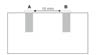
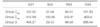
A self-curing polyurethane composite resin (Frame; Zirkonzahn, Gais, Switzerland) was used to simulate implant-supporting alveolar bone.29 The block was prepared for implant installation by drilling two holes on top of it, and 15 mm apart from each perimeter. Two internal connection-type implants with a diameter of 4.1 mm and a length of 10 mm (SSII; Osstem Inc., Seoul, Korea) were installed in the block according to the clinical protocol from manufacturer's recommendation. The implant was dipped in the mixed polyurethane resin, before it polymerized. Each implant was placed into the socket and secured in place with the same resin. Two implants were maintained to be parallel to each other during the installation. Polymerization of the resin served as osseointegration. The implant fixtures were referred to as implant A and implant B from left to right (Fig. 1). Fixture-level pick-up impression copings (SSICA480; Osstem Inc., Seoul, Korea) were assembled on the fixtures and an impression was taken with a custom tray and a regular-type polyvinylsiloxane impression material (Examixfine; GC, Tokyo, Japan). Implant analogs (SSFA480; Osstem Inc., Seoul, Korea) were placed and a vacuum-mixed type IV stone (SynaRock; DFS, Riedenburg, Germany) was poured into the impression to make a working cast. The superstructure was designed as a fixed dental prosthesis with its upper surface flat, providing 3 mm height space underneath the pontic base (Fig. 2). The specimens were fabricated on the working cast and adopted cement-retained design as experimental groups and screw-retained design as a control group. The cement-retained group was divided into two groups again, based on whether an internal adjustment was done or not. Each cement-retained group was named as Group Cadj, Group Cnon, respectively and the screw-retined group as Group S. Ten specimens were fabricated for each group (Table 1).
To manufacture specimens in the cement-retained groups, two ComOcta cemented abutments (SSCA485; Osstem Inc., Seoul, Korea) were connected onto the lab analogues in the working cast. After applying two coats of the die-spacer (Rubber Sep; Kerr Corporation, CA, USA), twenty pairs of acrylic resin (Pattern Resin; GC Corporation, Tokyo, Japan) copings were fabricated.35 A bar which was made of clear acrylic resin (Jet Acrylic self-curing resin; Lang Dental Mfg Co, IL, USA) with a cross-section of 4.8 mm × 4 mm was fabricated and a mold was made over this pattern using putty impression material (Twinz; Bisco Inc., IL, USA). Twenty acrylic resin bar replicas were manufactured by the mold. Two copings were put on each abutment and linked with the resin bar using wax. The same procedure was repeated until twenty pairs of copings were connected. The investment, burnout and casting procedures were performed according to the conventional lost-wax and casting technique. A Ni-Cr alloy (Vera-Bond II; Aalba Dent Inc., CA, USA) was used for casting.
Ten specimens were selected at random for Group Cadj. The internal surface of the each specimen was examined thoroughly using a silicone material (Fit-checker; GC Corporation, Tokyo, Japan) to detect high spots and pressure points. The spots where the silicone peeled away were considered to be premature contacts and were selectively removed using a stone bur. The other ten specimens were classified as Group Cnon and only large nodules apparent to the naked eye were eliminated.
The specimens in Group S were made at computer-aided design/computer-aided manufacturing (CAD/CAM) titanium milling center (Addtech Co. Ltd, Seoul, Korea). The working cast was placed on an optical scanner (White Light Automatic 3D Scanners; Solutionix DS, Seoul, Korea) to determine the positions and levels of the platforms. Data on the form of connection parts between abutments and implant fixtures were also imported. After the information was added to the computer file, the 3D design of the superstructure was completed. In accordance with this design, each framework was milled from one piece of titanium block by milling machine (UltraSonic 20 Linear; DMG, Bielefeld, Germany).
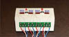
Four strain gauges (KFG-2-350-C1-11; KYOWA electronic instruments, Tokyo, Japan) were attached on the measurement model, mesially and distally adjacent to the implants with an adhesive (M-bond 200; Vishay Micro-Measurements, NC, USA). The strain gauges were referred to as SG1, SG2, SG3 and SG4 from the mesial one of the implant A to the distal one of the implant B (Fig. 3). A dynamic signal conditioning strain amplifier (CTA-1000; Curiotech Inc., Seoul, Korea) was connected and an analyzing program (DA-1700B; Cas Korea, Seoul, Korea) was used to measure and record the strains developed.
Prior to measurement procedure, the measurement model was ensured to be free of residual stress with the strain values showing zero. For the measurement in Group Cadj and Cnon, the ComOcta abutments were assembled onto the implants with a torque of 30 Ncm as the manufacturer's recommendation. Each specimens were cemented with temporary cement (Temp-Bond; Kerr, MI, USA).20 A defined load of 100 N was applied for 5 and a half minutes to the prostheses using a universal testing machine (5500 series; Instron, MA, USA) atthe middle point of the connector between two implants. The direction of loading was perpendicular to the implants. After the specimen was released, it was remained to bench set for few more minutes. The final strains were recorded until the strain values were stabilized. For the evaluation of Group S, the screw-retained specimens were secured with a driver by an equal sequence. The screws were fastened until resistance was felt and fastening torque was applied until torque wrench set to 30 Ncm was folded. The strain values were measured until it was stabilized and the final values were recorded for analysis.
For each group, the stabilized final strain values were collected for the statistical analysis. The measured strain was converted to absolute value for the evaluation. A repeated measures 2-factor analysis was performed for the comparison of the groups, at a level of significance of α=.05 (SPSS 14.0; SPSS Inc., IL, USA). The variance/covariance matrix of the dependent variables was evaluated whether they were circular in form.
RESULTS
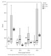
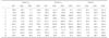
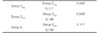
The strain values in µm/m for the three groups and different strain gauge locations were recorded (Table 2). Mean strain development at the different strain gauge locations ranged from 29.53 to 412.94 µm/m (Table 3). At each gauge location, the average strain was highest in the Group Cnon (Fig. 4). As the Huynh-Feldtepsilon was 0.757 and was to 1, and the repeated contreats were uncorrelated, the sphericity was confirmed for the result of this study. According to the repeated measures 2 factor analysis, the comparison between Group Cadj and Cnon exhibited significant difference (P=.008). While the difference was not significant, the mean strain developed on Group S specimens, a control group, was higher than that of Group Cadj and lower than that of Group Cnon (Table 4).
DISCUSSION
The highest strain was developed around the implants connected with the superstructures of Group Cnon. Implant-superstructure complex of Group Cadj was shown to be more passive than that of the other groups. The difference was significant between Group Cadj and Group Cnon. This indicates that an internal adjustment of an implant restoration is one of the critical factors to improve a passive fit of the prosthesis. Group Cnon showed higher strain than Group S. While the difference was not significant, this comparison illustrates that cement-retained designs do not always exhibit lower levels of stress than screw-retained designs. This is opposed to the reports in which several authors have demonstrated that the cement-retained prostheses are advantageous when it comes to passivity.21-26 The magnitude of strain development corresponds to the level of misfit of the restoration.29,36-39 Thus, removing undesirable contacts which can cause misfit is more important to achieve passivity, than selecting the type of retention.
If the misfit is obvious to be felt by the tactile sense, various attempts such as cutting, soldering, or even remaking the prosthesis can be done to correct the errors. In this study however, before adjusting the prostheses, every cement-retained specimen was evaluated to fit well without tilting or marginal opening. Therefore, the internal adjustments were performed to a very subtle level of correction. After examining the internal surface using Fit-Checker, only the spots where the Fit-Checker came off were removed selectively. The area near the margin, which had not been covered with the die-spacer, was preserved and set aside from adjustments to ensure the specimens in Group Cadj a reasonable amount of retention.
While the difference was not significant, prostheses from Group Cadj were more passive than those of Group S at the strain gauge locations of SG1, SG 3 and SG 4. The screw-retained superstructures in Group S were manufactured with the titanium milling technique by the CAD/CAM system. Although this method skips some procedures that can lead to a misfit, there still remains the impression and working cast fabrication procedure which could cause some errors. One of the shortcomings of the screw-retained type was its inability to adjust the prostheses during the delivery procedure.
When the screw is tightened, a compressive stress is inevitably generated and transmitted to the surrounding alveolar bone, in order to secure the abutment with the implant.40 In this study, Group S revealed particularly high mean strain values at SG1. During the procedure of the measurement model fabrication, the holes for implant fixtures were drilled by hand without the help of a milling machine for the purpose of reproducing a clinical situation. Accordingly, the vertical axes of two implants were not perfectly parallel and the vertical levels of the fixtures were not exactly equivalent. The horizontal part of the superstructure which links the two abutment parts was designed to meet at right angles with the vertical axis of implant B. Implant A was anchored at a deeper position and at acute angles to the horizontal axis. Consequently, since the connection part of each internal-type screw-retained superstructure was not exactly parallel, the strain developed on each strain gauge was not even. It is assumed that tapered internal surface of implant A might bear the extra compression force due to the increased angle between the horizontal plane of superstructure and the center line of connection part (Fig. 5).
Although the passive fit of an implant prosthesis is regarded as one of the important factors which affect the longevity of an implant treatment,41 the correlation between the mechanical fit of the framework and the biological influence on the surrounding tissue still lacks scientific evidences.9,42,43 However, the relationship between strain caused by the misfit and the biologic response of the surrounding tissue could only be discussed, after the in vivo assessment of the strain developmentis established.44 Further clinical studies and cadaver researches is needed to evaluate the strain development in the actual clinical settings.
CONCLUSION
Within the limitations of this study presented, the following conclusions were drawn. The cement-retained designs do not always exhibit lower levels of stress than screw-retained designs. The internal surface adjustment of a cement-retained implant restoration is essential to achieve passive fit.


 XML Download