

 PDF
PDF ePub
ePub Citation
 Print
Print


INTRODUCTION
All ceramic restorations have become more widely distributed due to their high esthetic potential and their excellent biocompatible properties.1-5 Today, many framework structures for prosthetic restorations are fabricated using CAD/CAM system, which means that a major part in the working sequence is carried out by means of industrial machines.6-8 Then frameworks can be fabricated more efficiently. Also, it is possible to achieve industrial quality standards, which are particularly important for ceramic materials. Every pore and imperfection is a potential starting point for cracks and thus for the clinical failure of ceramic restorations.9,10 The frameworks made of glass-infiltrated oxide ceramic fabricated in the slip technique exhibited large spectra of strength distribution related to the fabrication process resulting in a low Weibull modulus.11 Using the same ceramic material in the form of industrial prefabricated blocks and applying the milling technique increase the Weibull modulus of oxide ceramics, and thus the reliability of the restorations was significantly enhanced.11 However, the veneering material has been layered according to the conventional fabrication process of the metal-ceramic technique. According to ISO 6872 standards a minimum flexural strength of 50 MPa for veneering glass ceramics is required.12 The bond between veneering ceramic and zirconia framework is currently the subject of comprehensive investigations.13,14 The typical failure pattern of a veneering material in the daily clinical practice is known as ceramic chipping.15,16 This fracture pattern is associated with a thin layer of feldspathic porcelain that remains on the zirconia framework.15,16 This indicates a reliable bond of veneering ceramics to the framework, but also reveals a weakness of the veneering porcelain.8,9,15,16 A possible reason for the incidence of chippings may be found in the former limited CAD software options by which crown and fixed partial denture (FPD) frameworks could not be machined to an anatomically reduced form, which offers adequate support to the veneering material. In contrast many systems could offer only uni-thickness copings for crowns as well as bar-shaped connectors for FPDs. Therefore with these systems, veneering ceramic had to be applied in thick layers to accomplish functional and esthetic demands without any cusp support.8,17 For metal-ceramic restorations, it was reported that inadequate framework design represents one important reason for an unfavorable failure rate of the veneering material.18 Modern CAD/CAM-systems are able to provide a considerably better anatomically cut back framework design, thus future clinical long-term results may be more favorable.8,17 From an economical point of view, the esthetic and functional completion of crown and FPD frameworks involving traditional methods, such as the powder layering technique, appears to be inefficient. One possibility for increasing the cost effectiveness involves the industrial fabrication of glass ceramic mono-blocks and machining of the entire restoration by means of CAD/CAM technologies.19 In general these mono-block restorations use either leucite-reinforced glass ceramics with a flexural strength of around 100 - 150 MPa with mandatory adhesive cementation, or lithium-disilicate reinforced glass ceramics exhibiting a flexural strength of 350 - 400 MPa, with the option of conventional cementation. Therefore, the indication range is strongly limited to single crowns and small FPDs.20-22 The combination of a CAD/CAM-fabricated framework with CAD/CAM-fabricated veneering would be of major interest, especially if considerably stronger veneering ceramics can be applied. Recently, a new procedure for veneered all ceramic crown restorations using a CAD/CAM-fabricated high-strength zirconia coping and a corresponding CAD/CAM fabricated glass ceramic veneering material was introduced. Both corresponding parts of the restoration can be sintered together by means of a glass ceramic powder in one bake. It can be assumed that the new procedure of sintering core and veneering leads to an increase in mechanical strength compared to traditional techniques enabling a lower clinical chipping rate of the veneering material. The purpose of this in vitro study was to compare the fracture strengths of zirconia crowns veneered with various ceramic materials by various techniques.
MATERIALS AND METHODS
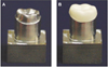
A silicone impression (Honigum mono, DMG, Hamburg, Germany) was made with a custom impression metal tray in order to duplicate the artificial anatomic resin tooth of a mandibular right first molar into improved stone model. A 1.2 mm, 360° chamfer preparation and occlusal reduction of 2 mm were performed on a stone model. To control volumetric reduction, a silicon impression (Exafine Putty Type, GC Co., Tokyo, Japan) was made prior to stone model preparation. Additionally, the preparation was completed with a surveyor (F1, DeguDent GmbH, Hanau, Germany) using a carbide bur (Komet H 356 RGE 103.031, Gebr. Brasseler, Lemgo, Germany), to ensure that the preparation had an 8° tapered angle. Forty-five model dies were fabricated in a titanium alloy by CAD/CAM system (Myplant™, RaphaBio, Seoul, Korea) in order to duplicate the prepared stone model. To ensure the correct preparation angle, all 45 titanium master dies were finished with the surveyor using a carbide bur. A master die was scanned and 45 zirconia copings were manufactured by a CAD/CAM system (Lava™, 3M ESPE, Seefeld, Germany) using pre-sintered zirconia (Lava Frame™ Crown & Bridge, 3M ESPE, Seefeld, Germany). A wall thickness of 0.5 mm and a virtual spacer layer of 10 µm were chosen. After the milling procedure the enlarged copings were removed from the CAM machine and final sintering was performed in a special sintering furnace. The copings were examined for deformation and debris, corrected if necessary and cleaned with steam. Each coping was seated on a definitive die. Copings were rejected if the margin was rated visually unacceptable by two investigators (one dental technician and one dentist). Undercontoured frameworks and frameworks which could be rotated on the definitive die under finger pressure were also rejected. New copings were fabricated on the same dies to replace the rejected specimens. Forty-five acceptable copings were achieved from a total of 48 copings. Next, the acceptable copings were adapted until the best possible fit was achieved. The adaptation was made by an experienced dental technician with a magnification of eight (Stemi DV 4, Zeiss, Barrington, NJ, USA) according to the literature.23 The sample of 45 copings was divided into three groups so that for each of the 15 testing models one adapted coping existed (Fig. 1).
1. Group LT: Layering technique
The traditional layering technique was applied to veneer the copings of the first group. A calibrated dental technician who was experienced in veneering metal or ceramic frameworks for 16 years produced the specimens. First a special liner (IPS e.max ZirLiner, Ivoclar vivadent, schaan, Liechtenstein) was applied onto the zirconia frameworks and fired in a calibrated ceramic furnace at a temperature of 960℃. A feldspathic porcelain (Vita VM9, Vident, Brea, CA, USA) was applied in a dentin-enamel-layering and fired at a temperature of 930℃. With a final firing, the porcelain was glazed and the restoration finished. One major goal of the study was to fabricate exact duplicates of these veneered crowns using alternative veneering techniques. Therefore an impression of each crown fixed onto the testing model (Fit checker II, GC Co., Tokyo, Japan) was taken using a putty silicone material (Exafine Putty Type, GC Co., Tokyo, Japan). These impressions were cut from buccal to lingual to get the fixed crown and the testing model removed.
2. Group HT: Heat pressing technique
First a layer of the system's liner (IPS e.max ZirLiner) was applied to the copings similar to Group LT and fired at a temperature of 960℃. Then the copings were fixed onto their testing models by a silicone material (Fit checker II). The impressions made from the outer surface of the crowns from Group LT were used to create the shape of the restorations. Both parts of the impressions were filled with wax (Nawax compact, Yeti Dental Products, Engen, Germany) in the area of the crown, and the testing models with the fixed copings were put into one part of the impression. The two parts of the impression were set together and the resulting wax-up was arranged onto the coping in order to obtain an equivalent veneering structure of the corresponding crown from Group LT. The wax surface was smoothed, finished and invested into a special investing material (IPS PressVEST, Ivoclar vivadent, schaan, Liechtenstein) in a muffle of size two according to the manufacturer's instructions. The wax was burnt out and the muffle was heated. The copings were overpressed by a special porcelain (IPS e.max ZirPress, Ivoclar vivadent, schaan, Liechtenstein), which had an appropriate coefficient of thermal expansion with respect to zirconia. After cooling, the investment was removed in a sandblasting unit using 50 µm glass beads at 2 bar pressure. The reaction layer formed during the press procedure was removed by immersing the crowns into HF solution (IPS e.max Press Invex Liquid, Lot H31070, Ivoclar vivadent, Schaan, Liechtenstein) in an ultrasonic cleaner for 5 min. Subsequently, the crowns were cleaned under running water for 3 min and dried. The pressing sprues and extrusion flashes were removed using a water cooled air-turbine without pressure to protect the porcelain from heat damage. Finally glaze paste (IPS e.max Ceram Glaze paste, Ivoclar vivadent, Schaan, Liechtenstein) was mixed with the respective liquid (IPS e.max Glaze and Stain Liquid, Ivoclar vivadent, Schaan, Liechtenstein) to the desired consistency, applied evenly on the crown shapes and fired at a temperature of 750℃.
3. Group ST: Sintering technique
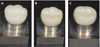
The first step using the sintering technique to produce comparable test specimens within the scope of this study, was to generate glass ceramic veneer caps which fitted onto the zirconia copings on one side and correspond almost exactly to the outer shape of the crowns fabricated by the other two techniques applied for Groups LT and HT. The objective to acquire an exact copy of the veneered restorations from group LT by CAD/CAM technologies was easily achieved. The copings of Group ST and the outer surfaces of crowns from Group LT were dimmed by applying a contrast spray (Dentaco, Bad Homburg, Germany). Each coping of group ST was scanned by a white-light scanner (Lava™ Scan, 3M ESPE, Seefeld, Germany) and treated like a prepared tooth, additionally the outer surface of each crown from Group LT was scanned. The CAD/CAM system used (Lava™ DVS Digital Veneering System, 3M ESPE, Seefeld, Germany) provided the function of a double scan. So the outer and the inner shape could be scanned, matched together and the CAD/CAM system permitted the manufacture of the space between both scans from a material of choice. Lava glass ceramic blocks are available for the CAD/CAM-system used. This ceramic is ideally suitable for the sinter bond technique with zirconia copings due to the appropriate match of the coefficients of thermal expansion. The internal dimensions of the veneer cap correspond to the external dimensions of the coping. A joining gap should be available on the internal aspect of the veneer cap to join the two components. The external dimension of the veneer cap corresponds to the shape of the full anatomical crown (Fig. 2).
The two components (CAD/CAM coping and CAD/CAM veneer) were joined by means of a low-fusing ceramic material (experimental connector material, 3M ESPE, Seefeld, Germany). Requirements of the connector material were a suitable CTE between the zirconia coping and the glass ceramic and an appropriate firing temperature, which would not deform or destroy the veneer cap made out of glass ceramic. The connector material was applied at a low viscous consistency to the internal aspects of the veneer cap. Subsequently, the veneer was fitted on the coping structure with slight pressure. This step was performed on the dies of the master model. Subsequently, excess of low viscosity ceramic material was removed with a brush. Since Lava™ DVS restorations were milled in a pre-crystalline state, they had to be subjected to a crystallization firing in a conventional ceramic furnace after milling. This firing cycle served simultaneously as the sinter bonding firing at a temperature of 850℃. Finally, the restorations were completed with one stain and glaze firing cycle at a temperature of 750℃.
After glaze firing, each crown from all groups was fixed onto its corresponding master titanium model by resin-modified glass ionomer cement (UniCem™ Cliker, 3M ESPE, Seefeld, Germany). The internal walls of the crowns were cleaned with steam and degreased (80% ethanol) while the surfaces of the master titanium models were aluminum oxide abraded (50 µm particle size, 0.5 bar pressure) and degreased prior to cementation. The resin-modified glass ionomer cement (UniCem™ Cliker) was mixed for 20s by a plastic spatula and the coping were filled with cement, and the cement was spaced out by a disposable brush until the complete surface was coated. The retainer was set back onto the definitive die with finger pressure, and the excess cement was removed. A special cementing device was used to ensure that the crown was loaded centrally at a force of 50 N for 10 min.24 All cementations were done by the same team of an experienced dentist, who sat the crowns onto the definitive die, and a dental assistant, who activated the capsule of cement and started the mixing procedure. All restorations were stored in distilled water at a temperature of 37℃ for at least 48h until they were loaded for the fracture test.
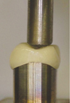
All crowns were put into the universal testing machine (Instron 5583, Instron, Norwood, MA, USA) at a 15° inclination relative to the long-axis and finally loaded until fracture occurred. Before the load was applied, the specimens were adjusted to the piston to ensure a three point contact between the stainless steel ball and the occlusal surface (Fig. 3). The load was applied with a 6 mm diameter stainless steel ball placed on the occlusal surface of the crowns and a crosshead speed of 0.5 mm/min.25,26 Fracture was defined as occurrence of visible cracks in combination with load drops and acoustic events or by chipping which made the crown clinically unusable. Calculations and statistical analysis were carried out using SPSS 20.0 for Windows (SPSS Inc., Chicago, IL, USA). The loads at fracture were registered, and differences between the groups were calculated using a one-way analysis of variance test at a significance level of 5%. Additionally a multiple comparison post hoc test (Student-Newman-Keuls) was performed to evaluate differences between the experimental groups.
RESULTS
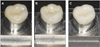
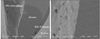
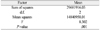
The mean and standard deviation of fracture strength values for the three experimental groups are shown in Table 1. Two failure types were observed: total fracture, through both core and veneer and partial fracture through the veneer only (chipping). Total fractures were more frequent in the Group ST (eight) while five total fractures occurred in the Group HT and two total fractures were observed in Group LT. In all instances of partial fracture, the fracture was cohesive within the veneer material (Fig. 4). Crowns fabricated with the sintering technique (ST) showed significantly higher fracture strengths compared to crowns made with layering technique (LT) and heat pressing technique (HT) (Table 2). The Student-Newman-Keuls test indicated two subgroups, which exhibited statistically significant differences (Table 3). Scanning electron microscope (SEM) pictures have shown interfacial bonding conditions between the connector materials, internal coping materials and external veneering materials (Figs. 5-7).
DISCUSSION
It has been suggested that test specimens should have the same critical flaws as crowns made for clinical use and the environmental influences should be reflected in the laboratory settings.27 The approach chosen in the present study was considered justified as the study design took aspects regarding test specimens, environmental influences and test mode into account. The recommendations concerning tooth preparation design, dimensions, and shape of the zirconia core are identical for crowns veneered with feldspar porcelain or heat pressed by glass ceramic.28,29 The approach for the new way of veneering was to produce identical restorations concerning dimension and core design.30 In all three groups, the cores were accomplished as if they were intended for clinical use. The veneer firing and the heat pressing procedure were performed according to the manufacturer's instructions, with appropriate dimensions and identical for all three groups. Cementations were made according to the manufacturer's recommendations, with resin-modified glass ionomer cement on titanium dies. According to Scherrer, increasing elastic modulus of the supporting material results in increased fracture strength.31 The elastic modulus of the supporting die was 200 GPa, superior to that of dentin which is 12 GPa.31 If natural teeth were used as the supporting model, the fracture strength of the crowns might have been lower.32 However, natural teeth would have been destroyed during the testing at the high fracture loads.27 The abutment material has a significant influence on the fracture load and increased them in this study. Similar loads have been described with titanium and chrome-cobalt abutments.30 The diameter of the loading piston influences the fracture load.33 This study used a similar diameter compared to most comparable studies to ensure the three-point contact of the piston to the occlusal surface of the specimen.30 This might be one explanation of the similar load-bearing capacity compared to previous studies.30 Loading conditions and cementation were identical for all specimens. Ceramic structures tend to fail because of surface tension, here cracks and flaws propagate by slow crack growth leading to the catastrophic failure.34 In all-ceramic systems, the flaw population (size, number and distribution) can be related to the material, or be affected by the fabrication process. Thus, it might be expected that the heat pressing introduces fewer flaws than layering, resulting in better strength properties, as it is a more controlled procedure. By comparison, the layering technique is more sensitive and subject to variability due to the individual building and firing procedures. Nevertheless, no statistically significant differences were found in the fracture loads between Group LT and HT. A study which compared fatigue of veneered and heat pressed zirconia crown systems also found no statistical difference between veneering by layering and by heat pressing in terms of mechanical stability.30,35 The homogeneity and the distribution of flaws may be similar between test Groups LT and HT. However, there were five catastrophic failures reported in the heat pressed group, which might be caused by the greater strength of the heat pressed veneer material and structure. It is reasonable that the failure mode of zirconia based all ceramic restorations veneered with a relatively weak porcelain - assuming a good bond - tends more to cohesive chipping of the porcelain at lower fracture loads whereas higher strength veneer material provokes to a certain extent total fracture at higher loads. Thus, the relatively weak veneering porcelain of the specimens from Group LT led to cohesive fractures, where a thin porcelain layer still remained on the zirconia coping. This type of failure indicates the good interfacial bond between the core and the veneer material that is critical for the success of these composite structures.36 The fracture strength of specimens with a sintered veneer cap was significantly higher than that of the other groups tested. Two main reasons might be responsible for the greater strength. First the glass ceramic used for the sintered veneer cap (Lava™ DVS) has a greater flexural strength in comparison to the veneering porcelain used for the layering technique and the heat pressing material. The number of total fractures also expresses the stability of the zirconia-based crowns in combination with the sintered veneer cap. Eight of the 15 specimens failed catastrophically at a very high fracture load. Second the CAD/CAM process uses high quality material with a minimum of flaws compared to the manual procedures of veneering or heat pressing. The fact that seven cohesive fractures were observed in Group ST also indicates that a good interfacial bond is achieved using the sintering technique. Catastrophic failure as a result of contact loading has made it difficult to identify whether cone cracking or subsurface damage was responsible. It is supposed that both processes may occur at the failure site as reported by previous studies.36 In contrast to previous studies, fractures of the zirconia core occurred in all groups. This might be explained by the greater flexural strength of the veneering materials. The specimens of Group ST were fabricated merely by the CAD/CAM technique, which leads to a significant reduction in the fabrication time for such restorations. From the economical point of view, the esthetic and functional completion of crown and FPD frameworks involving traditional methods, such as the powder layering technique, appears to be inefficient. Applying veneering porcelain by brush in several bakes is time consuming and costly. Sintering a CAD/CAM fabricated veneer cap made from glass ceramic to zirconia was reported to offer high mechanical stability in vitro.30 The increase in the strength of such systems may result in greater clinical reliability of restorations. All groups evaluated showed greater fracture loads than most available literature and exceeded the maximum chewing forces.10,20,35 However, clinical failure of zirconia based restorations was reported.16,17,37,38 It is supposed that fatigue has a major effect on the mechanical stability and explains the high values compared to similar studies, such as fatigue, not taken into account in this study.10,35 The abutment material, as mentioned above, has a significant influence and increased the fracture load in this study.31,32 Similar fracture loads have been reported with titanium abutments.39 The standard deviation of up to 30% was in the same range or higher compared to similar studies.10,20,30,35 This can be explained by the design of the specimens as they were designed as crowns for clinical use in this study. Other studies reporting lower standard deviations used more simplified shapes of the occlusal surface.10,35 Appropriate software has to be developed to ease the CAD phase for the construction of veneer caps for FDP frameworks. However, CAD/CAM manufacturers have to provide the prerequisites regarding the software and accuracy in the milling process before this technique can be widely advocated for immediate implementation in the market.6,40-42
CONCLUSION
According to the results of this study heat pressing glass ceramics or layering feldspathic porcelain in order to veneer zirconia frameworks did not show significant differences in the fracture resistance of zirconia-based single crowns, although different fracture patterns considering partial or total fracture could be observed. However, the sintering of a CAD/CAM generated glass ceramics veneer cap to the zirconia core leads to a significant increase of mechanical stability. This enhances the clinical reliability of zirconia-based restorations.
Within the limitations of this in vitro study, the sintering technique of a CAD/CAM generated glass ceramics for veneering materials of zirconia coping is strongly recommended. This reduces the potential for chippings of the veneering ceramics of zirconia restorations. Additionally this technique leads to an extremely cost-effective fabrication of all ceramic veneered crowns merely using CAD/CAM facilities for the production of the two parts, which have to be joined by only one sinter firing procedure.


 XML Download