

 PDF
PDF ePub
ePub Citation
 Print
Print


INTRODUCTION
Imprecise implant prostheses may result in mechanical complications such as screw loosening, fracture of the prosthesis or implant components,1 or biological complications such as loss of osseointegration and marginal bone loss.2
An impression procedure that reproduces the intraoral relationship of implants is the first step in achieving an accurately fitting prosthesis. Two commonly used implant impression techniques are the closed tray and the open tray techniques. In the closed tray technique, when the impression is removed from mouth, the impression copings remain attached to the implants intraorally, whereas in the open tray technique, the impression copings are removed from the mouth along with the impression. The accuracy of impression techniques has been in dispute. Humphries et al.3 reported that the closed tray technique yielded a higher correlation to coordinate values on the definitive cast than open tray technique. In the open tray technique, splinting impression copings are thought to be important for accuracy in many studies.4-10 On the other hand, a number of studies have shown no significant difference in the accuracy between acrylic resin-splinted and unsplinted impression techniques.3,11-13 Some studies even reported that the unsplinted technique was more accurate than the splinted one.14,15
Most research has focused on the accuracy of techniques with parallel implants,3-15 but nonparallel implants are commonly encountered in clinical situations. For this reason, the investigators evaluated the nonparallel condition, with some finding no significant difference between the accuracy of the closed tray technique and unsplinted open tray technique at up to 15 degrees of angulation.16,17 Others reported that the unsplinted open tray technique was more accurate than the closed tray technique at 15 and 10 degrees of angulations.18,19 In the open tray technique, Choi et al.20 found no statistically significant difference between splinted and unsplinted impression copings at 8 degrees of angulation. Assuncao et al.21 reported that the splinted technique was more accurate than the unsplinted technique.
Several technical trials to achieve more accurate open tray impressions for patients with multiple implants are reported in the literature. Assif et al.9 used impression plaster as a splinting material other than autopolymerizing acylic resin. Assif et al.6 splinted impression copings directly to the impression tray. Vigolo et al.7,22 modified square impression copings with airborne particle-abrasion and coated them with impression adhesive. In a single-tooth implant impression, Vigolo et al.22 used an abutment as an impression coping, and concluded that a more accurate impression was achieved. Clelland23 used a bone-simulated model to study the difference in the strain generated by conventional frameworks and Abutment Luting frameworks, and reported a significant reduction in the magnitude of the strain with the resin-luted frameworks.
The purpose of this study was to compare the impression accuracy of a proposed abutment-framework (A-F) impression technique (using cement-on crown abutments as impression copings and a metal framework and resin cement as splinting materials) with that of previously established closed tray and resin splinted open tray techniques, and to evaluate the effect of angulation on the accuracy of these 3 techniques using angulated 3-implant definitive casts.
MATERIAL AND METHODS
Fabrication of the reference frameworks and the definitive casts
Three preliminary casts (2 cm × 5 cm × 2 cm) were fabricated with dental stone (Neo Plum stone; Mutsumi Chemical Industries Co., Mutsumi, Japan). In each cast, 3 holes were made 10 mm apart from edge to edge on the top surface using a milling machine. In all 3 casts, the center hole was made at right angle to the top surface of the cast. In the first cast, the left and right holes were parallel to the center hole. In the second cast, the left hole was angulated 15 degrees posteriorly and the right hole was anglulated 15 degrees anteriorly relative to the plane for a combined 30 degrees of angulation. In the third cast, the left hole was angulated 15 degrees posteriorly and the right hole was angulated 25 degrees anteriorly relative to the plane for a combined 40 degrees of angulation. Three implant analogs (Implant replica; Brånemark system, Nobel Biocare, Göteborg, Sweden) were secured in the holes with autopolymerizing acrylic resin (Orthojet; Lang Dental Manufacturing co. Inc, Wheeling).
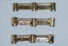
Three reference frameworks simulating bar attachment prostheses were waxed with 3 non-hexed UCLA Abutments (Goldadapt abutmemt, non-engaging; Brånemark system, Nobel Biocare, Göteborg Sweden) on each preliminary cast and then cast in type IV gold alloy (G45; Solomondent, Anyang, Korea; Fig. 1).
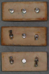
Polyvinylsiloxane (Aquasil Ultra XLV regular set light body, heavy body soft putty regular set; Dentsply De Trey Gmbh, Konstanz, Germany) pick-up impressions were made with custom trays on the preliminary casts, using the reference frameworks. To fabricate accurate definitive casts, 3 implant analogs were connected to the reference frameworks embedded in the impressions, and the impressions were poured with type IV dental stone (GC Fujirock; GC Europe, Leuven, Belgium). This procedure was similar to that used in previous studies 4-6,9,20 for fabricating definitive casts (Fig. 2). To expose the top surface of analog for accuracy assessment using a light microscope, a soft tissue cast of 5 mm thickness was fabricated with heavy body polyvinylsiloxane impression material before pouring of dental stone, and transferred to experimental definitive casts.
Fabrication of custom trays
One base former and 30 custom trays were fabricated for each of the 3 definitive casts. To fabricate the base former, 3 layers of baseplate wax spacers (Plate paraffin wax; RUBY, Tokyo, Japan) were placed on the lateral surface of the definitive casts, and tray resin (Vertex Trayplast NF; Dentimex, Zeist, Netherlands) was applied with a thickness of 2 mm. The outer surface of the base former was trimmed and inner surface wax spacers were replaced with heavy body polyvinylsiloxane impression material (Aquasil Ultra XLV heavy body soft putty regular set; Dentsply De Trey Gmbh, Konstanz, Germany).
To fabricate the custom trays, 2 layers of baseplate wax spacers were placed on the assembly of the definitive cast, base former and impression copings to ensure a uniform thickness of impression material. An irreversible hydrocolloid impression (Jeltrate regular set, Hamm Moor Lane, England) was made and poured with heavy body polyvinylsiloxane impression material. Ten trays for each technique were made on these polyvinylsiloxane casts (Aquasil Ultra XLV heavy body soft putty regular set; Dentsply De Trey Gmbh, Konstanz, Germany) for a uniform inner surface. Before impression making, tray adhesive (VPS tray adhesive; 3M ESPE, Seefeld, Germany) was painted inside each custom tray and allowed to dry for 15 minutes.
Impression procedure
For all 3 impression techniques, light body polyvinylsiloxane impression material (Aquasil Ultra XLV regular set light body; Dentsply De Trey Gmbh, Konstanz, Germany) was syringed around the impression copings on the definitive casts. Heavy body polyvinylsiloxane impression material was mixed by hand and dispensed inside the custom trays. The custom trays were seated with finger pressure and the impressions were allowed to polymerize for 10 minutes at room temperature.
In the closed tray impression group, closed tray impression copings (Impression coping closed tray; Brånemark system, Nobel Biocare, Göteborg Sweden) were used (Fig. 3A). The impression and custom tray was separated from the definitive cast. Impression copings were removed 1 at a time from the definitive cast and attached to implant analogs. These assemblies were inserted into the corresponding position in the impression.
In the resin-splinted open tray impression group, open tray impression copings (Impression coping open tray; Brånemark system, Nobel Biocare, Göteborg Sweden) were splinted with autopolymerizing acrylic resin (Pattern resin; GC Corporation, Tokyo, Japan). The acrylic resin splint (7 mm × 7 mm thickness) was fabricated on a duplicate cast obtained by the closed tray technique and was allowed to polymerize for 15 minutes before being removed from the cast. Fifteen minutes before impression making, the acrylic splint was sectioned with a 0.3 mm thickness disc (Ultra disks; Sejong, Seoul, Korea) and reconnected on the definitive cast with an incremental application to minimize polymerization shrinkage (Fig. 3B).
In the A-F impression group, straight and angled cement-on crown abutments (15 degree Esthetic abutment 1 mm, Esthetic abutment 1 mm, 25 degree TiAdapt RP; Brånemark system, Nobel Biocare, Göteborg Sweden) were used instead of impression copings. The cast metal framework and resin cement were used as splinting material. Straight and angled abutments were connected to corresponding analogs on duplicate casts obtained by the closed tray technique. Metal frameworks simulating repositioning jigs were waxed and cast in base metal alloy (Verabond; Albadent, Milford) at each of three angulations. The metal frameworks were cemented on the cement-on crown abutments on the definitive casts with resin cement (Superbond C&B; Sunmedical, Tokyo, Japan; Figs. 3C and 3D). The cement was allowed to polymerize for 20 minutes at room temperature. Pick-up impressions with custom trays were made using these abutment-framework assemblies. Assemblies could be easily separated by heating with an alcohol lamp.
All 90 impressions were poured with type IV dental stone according to the manufacturer's instructions (water/powder ratio: 100 g / 20 ml) and allowed to polymerize for 60 minutes. All duplicate casts were stored at room temperature for minimum 24 hours before measurement were made.
Measurement of accuracy
Vertical gaps between UCLA abutments of reference frameworks and implant analogs of duplicate casts were measured with a light microscope with image processing (Accura 2000, INTEK PLUS, Deajeon, Korea) under 240× magnification. The accuracy of the light microscope was ± 0.1 µm (Fig. 4).
To simulate the one-screw test, a single abutment screw (Abutment screw Brånemark system RP; Nobel Biocare, Göteborg Sweden) was tightened to 10 Ncm with a digital torque driver (MTG50; MARK10, Hicksville) to each of the analogs sequentially. Vertical gaps of the analogs were assessed in anterior and posterior directions for each duplicate cast. Since there was a relatively large difference in vertical gaps between the screwed analog and unscrewed analogs, only the following data were statistically analyzed: center analog screw tightening with measurement of the outer analogues (Fig. 5A), and 1 outer analog screw tightening with measurement of the other outer analog (Fig. 5B). Gap values were analyzed with the SPSS program (v 12.0) using analysis of variance and the Tukey test at a .05 level of significance.
RESULTS
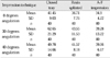
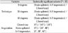
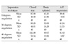
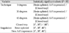
The vertical gaps in the outer analogs after the center analog was tightened (Fig. 5A), are shown in Table I. Values were analyzed statistically with two-way ANOVA (Table II) and the Tukey test (Table III). The vertical gaps in 1 outer analog when the other outer analog was tightened (Fig. 5B), are shown in Table IV with statistical analysis using two-way ANOVA in Table V, and the Tukey test in Table VI. The closed tray technique showed significantly larger vertical gaps than the two other techniques (Tables I, III, IV and VI; P < .05). The A-F impression technique showed smaller means and standard deviations in vertical gaps than the resin-splinted open tray technique (Tables I and IV). The effect of techniques, the angulation, and the interaction between the techniques and the angulation were statistically significant (Tables II and V; P < .05). The angulation of the implant analogs in the definitive cast influenced the vertical gaps of the closed tray technique and the resin-splinted open tray technique when the center analog was tightened (Table III; P < .05), and influenced those of the closed tray technique when the outer analog was tightened (Table VI; P < .05), but it did not affect the A-F impression technique (Tables III and VI; P > .05).
DISCUSSION
Most research has focused on the accuracy of impression techniques with parallel implants,4-15 and only a few studies have evaluated impression methods for nonparallel implants.16-21 A number of studies reported that there were no significant differences between the closed tray and open tray techniques,16,17 or between unsplinted and splinted open tray techniques at up to 15 degees of angulation.19,20 Therefore, in this study, impression techniques were evaluated for accuracy using relative angulation degrees of 0, 30 and 40 degrees. Data were collected also on the new A-F impression technique.
Previous studies evaluated vertical gaps using a traveling microscope. De La Cruz et al.13 showed means ranging from 50 µm to 100 µm in parallel 3-implant conditions. Assif et al.5 showed means of approximately 20 µm in 5-implant conditions. In this study, the vertical gap results had means ranging from 34 µm to 112 µm, with a difference of 10-30 µm. Dentists can detect differences in the range of 30 µm in the fit of a framework on multiple implants.5 It is interesting that all impression techniques showed mean vertical gaps above 30 µm.5 This implies that the passive fit of suprastructures may be unattainable, and establishment of a clinically acceptable range of vertical gaps is more important.
The A-F impression technique showed smaller means and standard deviations in vertical gap than that of the resin-splinted open tray technique (Tables I and IV) and the A-F impression technique was not affected by implant angulation (Tables III and VI. Thus, the A-F impression technique was more accurate and less variant in impressions for implant prostheses. It also showed more suitable and stable results in situation with angulated implants.
This study showed that the resin-splinted open tray technique reproduced the position of analogs more accurately than the closed tray technique. These results agree with previous investigations that emphasized the splinting of impression copings.4-10 However, the results do not agree with Humphries et al.3, who reported greater accuracy with the closed tray technique.
One limitations of this study is the failure to account for the setting expansion of dental stone. This could be a cause of vertical gaps between the implant analogs in the definitive cast and the reference framework. Rotational and horizontal error could not be detected in this study because of the use of non-hex UCLA abutments. After assembly of the implant analogs, the closed tray impression copings were inserted to impression material. Then, a soft tissue cast was reconnected to the impression to expose the platform of the analog. Possible distortion at this step could explain the relatively large vertical gaps in the closed tray technique.
The A-F impression technique in this study could be applied to a clinical situation using the following steps. Cementation-type abutments were milled, and a metal framework was fabricated on the preliminary cast that was obtained with a closed tray impression. These milled abutments were connected to implants in the patient's mouth, and the metal framework was cemented with resin cement. A pick-up impression was made using this abutment-metal framework assembly as the splinted impression copings.
This method is similar to one that involves luting frameworks to implant components to achieve better fitness in implant prosthodontics,23 but the new method is carried out at the impression stage, before definitive prosthesis fabrication. We suggest that this technique has several possibilities for improving the accuracy of impressions. Generally, cement space has a smaller thickness than that of disc-sectioned space (250 µm),13 So the effect of polymerization shrinkage of resin might be reduced by this technique. Metal frameworks have a greater flexural modulus than the resin splint used for pick-up impressions, so this technique could be more resistant to distortion forces caused by impression removal, polymerization shrinkage, and the setting expansion of dental stone.
The A-F impression technique has several expected clinical effects in addition to impression accuracy. Registration of jaw relation can be carried out using the metal framework during the impression appointment. For retrievable cement-retained implant prostheses, the impression procedure can be repeated for ill-fitting frameworks, without sectioning and soldering the metal framework. Comparison of the abutment-prostheses margin to the gingival level, and examination of the orientation of the screw access holes of the prostheses can be carried out before fabrication of the definitive prostheses. Cementon crown abutments used in the impression stage can also be used in the definitive prostheses.
CONCLUSION
In this study, the vertical gap was measured for 0, 30 and 40 degree angulated 3-implant definitive casts, and analyzed statistically to compare the impression accuracy of a proposed A-F impression technique to conventional closed tray technique and resin-splinted open tray techniques. Within the limitations of this study, the following results were drawn.
1. The A-F impression technique and the resin splinted open tray technique showed significantly smaller vertical gap than that of closed tray technique (P < .05).
2, The closed tray and the resin splinted open tray technique showed significantly different vertical gap according to angulation of implant (P < .05).
3. The A-F impression technique did not show significantly different vertical gap according to angulation of implant (P > .05).


 XML Download