

 PDF
PDF ePub
ePub Citation
 Print
Print


INTRODUCTION
Dental implant therapy has been widely used for the restoration of partially and fully edentulous patients.1 It is essential for long-term successful implant prostheses to achieve a passive fit between the fixture and the superstructure.2 A passive fit is defined as a very precise surface contact for the metal and it distributes functional load uniformly.3
Obtaining an absolute passive fit is practically impossible,4 and the behavior of the bone tissue around the implants supporting relatively ill-fitting prostheses remains controversial.5-8 Nonetheless, it is still universally accepted that the prosthesis misfit should be minimized,9 and accurate impressions are the first step in minimizing the misfit.
To date, many authors have investigate the factors affecting the accuracy of the implant impressions, such as the type of impression copings, the necessity and method of splinting the impression copings, surface treatment of the impression copings, direct or indirect impression techniques, the use of different impression materials, and angulated implants.10
Previous studies have concentrated on external connected implants that are positioned parallel, but generally, the implant fixture is not positioned parallel in clinical applications. Additionally, internal-connection implants have longer walls of relative parallelism that could make the withdrawal of an impression more difficult, resulting in the transfer of a higher level of stress to the impression copings during the impression procedure.11
Clinically, short impression copings are needed in situations where there is an insufficient interocclusal space, such as the posterior teeth area or patient with limited mouth opening. This impression coping has become commercially available for various implant companies. However, a smaller portion of the coping is exposed, lowering the stability of the impression coping in the impression material and, therefore, affecting the accuracy of the impression.12
There are a few studies which have investigated the influence of the length of the impression coping on the accuracy of the angulated implants.
Therefore, the purpose of this study was to investigate the effect of the type and length of the impression coping on the accuracy of the angulated internal-connected implant impression.
MATERIALS AND METHODS
Implant analogs (GS III® Fixture Lab Analog Standard, Osstem, Korea) and vinyl polysiloxane impression materials (Imprint III®, 3M ESPE, Germany) were used in this study.
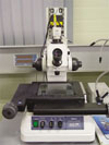
The experimental model was fabricated using Type IV gypsum (Fujirock® GC, Belgium). A torque wrench (TWMW, Osstem, Korea) was used to connect the analog and the impression copings. A measuring microscope (MF-A1010, Mitutoyo, Japan) was used to examine the distance of analogs (Fig. 1).
1. Fabrication of metal master cast
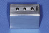
The metal master model (length: 4 cm, width: 2 cm, height: 3 cm) was fabricated using a milling aluminum block. Three holes with a depth of 9 mm were made at 10 mm intervals in order to embed the analogs. The center and lateral holes were parallel and the other one was at a 10° mesial angulation. The surface was well polished and did not affect the removal of the impression material. The analogs were positioned into the holes using a milling machine with Superbond C&B (Sun Medical, Japan). The top of the analog was positioned 1 mm above the model (Fig. 2).
2. Fabrication of individual tray
After connecting the impression coping to the master model, two sheets of baseplate wax were applied to provide space for the impression material. Then the alginate (Jeltrate regular set, Hamm Moor Lane, England) impression was taken in order to reproduce the master model with putty type PVS (Exafine®, GC corperation, Japan). With this mold, the custom impression tray was fabricated using a light-polymerizing impression tray material (Lightplast, DreveDentamid, Germany) and cured in a light-curing machine (Unilux AC, Kulzer Hereaus, Netherlands) for 5 minutes. Retention holes were made on the side of the tray in order to retain the impression material, and occlusal holes were made for the guide pin of the pick-up type impression coping. Tray adhesive (VPS Tray Adhesive, 3M ESPE, Germany) was applied and dried for 15 minutes.
3. Fabrication of experimental model
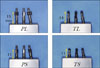
The impression copings were classified by their type and length (Fig. 3). P and T were used to represent the pick-up and transfer types of impression coping. Additionally, L and S were used to symbolize long and short coping lengths. A total of four groups (PL, PS, TL, and TS groups) were made, and in each group, 10 impressions were made so that 40 experimental models existed.
The impression coping was connected to the metal master cast. The light body material (Imprint III®, 3M ESPE, Germany) was injected around the impression coping, and at the same time, the heavy body material (Imprint III®, Penta™, 3M ESPE, Germany) was filled in the individual tray. The tray was positioned on the model for 8 minutes (twice the time of polymerization in mouth). Then the overflow impression material was wiped away using a finger.
(1) Pick-up type (PL group, PS group)
After the polymerization, the tray was removed by loosening the guide pin with a hex driver. Then the fixture analog was connected to the impression coping that was left in the impression material.
(2) Transfer type (TL group, TS group)
The tray was removed after the polymerization of the impression material. The impression coping that was removed from master cast was connected to the analog by hand and then repositioned into the inner position of the impression material.
The Type IV dental stone was poured according to the manufacturer's instructions (water/power : 20 ml/100 g). After the stone setting, the tray was separated from the model. After at least 24 hours had elapsed, the accuracy was measured.
4. Measurement of distance
The distance between the analogs of the master model and the experimental model was measured using a measuring microscope (MF-A1010, Mitutoyo, Japan) and the Hanra measure program (Hanra precision ENG, Korea). This microscope had a magnification of 100× and an accuracy of ± 0.5 µm. D1 was defined as distance from the top center of the central analog to the top center of parallel positioned analog in the master model, and D2 was the distance to the center of mesial angulated analog in the master model (Fig. 4). And, d1 was defined as distance from the central analog to parallel positioned analog in the experimental model, and d2 was the distance to the mesial angulated analog in the experimental model.
5. Statistics analysis
The SPSS program (SPSS® statistics, IBM, USA) was used to determine the mean and standard deviation of the error rate. The ANOVA test was used to determine the significance of the type, the length, and the angulation of the impression copings, and a value of P < .05 was used to judge the statistical significance.
RESULTS
The distances between the analogs in the master model and the experimental model were measured. The error rate (ER) was calculated to compare each group (Table 1).
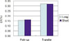
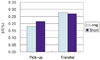
The mean (standard deviation) values in D1 were 0.155% (± 0.054) for the PL group, 0.162% (± 0.112) for the PS group, 0.321% (± 0.177) for the TL group, and 0.320% (± 0.193) for the TS group. The mean (standard deviation) values in D2 were 0.180% (± 0.076) for the PL group, 0.215% (± 0.091) for the PS group, 0.277% (± 0.204) for the TL group, and 0.269% (± 0.355) for the TS group (Fig. 5, 6).
The error rates in D1 and D2 decreased in the order of the PL, PS, TS, and TL groups.
A significant difference was observed between the type of impression coping in D1 (P < .05) but not in D2 (Table 2).
The lengths of the impression coping were not significantly different for both D1 and D2 (Table 2). The PL group exhibited the lowest error rates among all of the groups.
The error rates did not differ between D1 and D2.
DISCUSSION
Typically, two methods, the strain gauge method and measuring method are used to compare the accuracy of the impression. In this study, the relative difference in the distance was measured using a two-dimensional measuring microscope. The measuring method consisted of setting a measuring point as the x-axis and the y-axis and then determining the linear distance using the Pythagorean theorem: d2 = Δx2 + Δy2.
The distance between the analogs was set at 10 mm based on the clinical distance of the molars in the posterior area. The mesial angulated analog was tilted 10°. The internal connected implant used in this study could have a maximum angulation of 22° because of its 11° internal tapered surface. Therefore, a medium value of about 10° was used. The measuring point of each analog was the top center of the central analog.
The error rate was used to compare each group. Barrett13 measured the absolute distortion value of each implant using an external measurement point because a difference between the distance of the two points (10.0 and 9.8 mm) due to angulation. However, in this study, the relative displacement was measured using each implant as the other implant's measuring point in order to obtain more clinical results.14
Vinyl polysiloxane and polyether impression materials are recommended for the implant impression.15,16 In this study, the vinyl polysiloxane impression material was used in a one-step method. Wenz et al.17 reported that the one-step vinyl polysiloxane method was more accurate than the two-step method or medium body vinyl polysiloxane or polyether methods.
In this study, D1 was defined as the distance between the top middle of the center analog and the parallel positioned analog, and D2 was defined as the distance from the center to the mesial angulated analog. The TL and TS groups exhibited significantly high error rates in D1, with values of 0.321% and 0.320%, respectively (P < .05). The error rates for the PS and PL groups were 0.162 and 0.155%, respectively. The TL group exhibited the highest error rate of 0.277% in D2, followed by the TS, PS, and PL groups. No significant difference was observed between these error rates (P > .05).
In this study, the impression copings were divided into two types of coping, pick-up and transfer. The pick-up type exhibited a lower ER than the transfer type for D1 and D2 because it was fixed in the impression material and, therefore, more stable during the removal of the impression material and the pouring of gypsum. On the other hand, the transfer type was repositioned into the impression by connecting the analog out of the mouth.18-21
However the difference was not statistically significant in D2 (P = .055). The internal connected implants that were used in this study had a larger contact surface than the external connection, and the 10° mesial angulation was relatively large, especially in this system. Therefore, the impression material was easily distorted during the separation of analog, and the pick-up type of impression coping caused friction on the internal interface.11
The lengths of the impression coping were not significantly different in both D1 and D2. Lee et al.12 reported that the implant depth (4 mm) did not affect the dimensional accuracy of the putty and the light-body combination VPS impressions for the exposed length of the impression coping. These results suggested that short impression coping length (11 mm) satisfied the minimum length for the impression material, and this length can be utilized to make impression copings in the future.
In a direct comparison, the distances of D1 and D2 were not significantly different. Choi11 and Conrad et al.22 also reported the conditions were not different when two or three implants were used. However, Assuncao et al.16 and Carr18 reported that the parallel model was more accurate than the angulated implant when four or five implants were used.
Consequently, the accuracy of the master cast was mainly affected by the type of impression coping rather than the length. Therefore, accurate master casts could be fabricated using the pick-up type of impression coping, regardless of the length.
In this study, the mean error rate ranged from 0.155 - 0.321%. However, an inherent error was caused by the experimental material itself, so a careful interpretation was needed. Ma et al.23 reported that the gap between implant components is 22 - 100 µm, and Rubenstein and Ma24 reported the 23.1 - 51.7 µm gap.
This study was limited by the lack of a 3-dimensional analysis, which included the rotation of the axis, because a 2-dimensional measuring microscope was used. Furthermore, this experimental study is difficult to apply to different clinical situations. Therefore, an additional study is necessary in order to examine a multiple implant arrangement, with various angulations, depths, and other impression materials in the future.
CONCLUSION
The following conclusions were drawn from the distance measurements between the analogs in the master model and the experimental model.
The pick-up type impression coping had a more accurate model than the transfer type in the parallel group.
The accuracy of the models did not differ according to the length of the impression coping of at least 11 mm.
The parallel group and the 10° mesial angulated group were not different with respect to the accuracy of the model.


 XML Download