

 PDF
PDF ePub
ePub Citation
 Print
Print


INTRODUCTION
Various connection types between implant and abutment are used. They determine joint strength, joint stability and stability of location and rotation. It is critical to and synonymous with prosthetic ability.1 Screw is the original and most commonly used method for connecting abutment to implant. However, screw loosening and screw fracture are major disadvantage of this method. Goodacre et al. mentioned screw loosening as the most frequent complication.2 Screw loosening occurs when occlusal force excesses preload or when it comes to creep deformation on screw-implant interface.3 Jemt et al. reported that screw loosening can cause more serious problem with single tooth restoration.4 Also screw loosening appears to be a factor of other components' failure5 and some authors proposed to re-tighten the screw every 5 years.6
Locking taper connection type abutment has been introduced alternative to screw-retained abutment systems. It has 1 - 2 degree tapered post that fits into a smooth mirror-image shaft, without any screw.1 Surface of the abutment for Locking taper connection type appears to be smooth, but actually it's not. Retention depends on the frictional resistance through morse taper. The high frictional force comes out of high contact pressure by relative slip between two surfaces. As a result, surface oxide layers break down, and the asperities fuse (known as cold welding). Therefore gaps between two surfaces disappear.7
Locking taper connection type implant with conical abutment has potential for microbial seal, prevention of joint opening, distribution of lateral loading deep within the implants and buffering vibration. Also it has high resistance to lateral force owing to fin shape increasing surface of the fixture.
However it is impossible to place abutment precisely and repeatedly without an index form. Also even the connections are stable, it lacks flexibility.1 Through clinical study about reliability of Locking taper, Chapman et al.8 reported occlusion and imprecise prosthesis can result in abutment fracture in screw-retained abutment. After analyzing 1,757 cases of Bicon® implant no problem with retention or fracture of abutment were found. However, some losses of abutments were reported, which were no big deal because they could be reconnected easily.
Unlike screw-retention type, abutment-fixture retention in Locking taper connection depends on the frictional force so it has possibility of abutment to sink. Thus, in this study Bicon® implant system which is one of the conical internal connection implant system was used, and loading was applied to the abutments connected to the fixture and the amount of sinking was measured.
MATERIAL AND METHODS
1. Material
1) Implant fixture and abutment
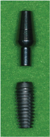
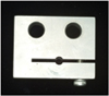
In this study, 4.5 × 11 mm (Uncoated implant 3.0 mm well) sized fixture of Bicon® Implant System (Bicon Inc, Boston, USA), a conical internal connection implant system, was used. For the abutment, locking taper connection type of conical abutment (5.0 × 6.5 mm 0° Non-Shouldered Abutment 3.0 mm Post) was used (Fig. 1).
2) Loading application instrument
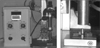
It was designed to tap with load of 20 kg vertically until no more sinking was occurred (Fig. 2).
2. Methods
1) Connecting abutment to the implant fixture
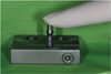
The abutment was slightly attached to the fixture with no pressure and this state of length was treated as a reference length of abutment-fixture (Fig. 3).
2) Loading conditions
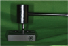
Loads in the clinical order of connecting locking taper connection type abutment to the fixture were applied. First, the abutment was connected to the fixture with finger force (Fig. 3). Then it was tapped with a mallet for 3 times (Fig. 4) and loads of 20 kg corresponding to masticatory force were applied successively.
A jig, fitting into the fixture, was made to avoid any movement of the fixture (Fig. 5).
In order, a finger force, 3 times of malleting force, and vertical load of 20 kg were added to every of 10 connected with fixtures abutment. Loads of 20 kg were added until there was no more sinking of the abutment.
3) Measuring the amount of sinking
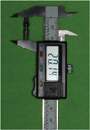
0.01 mm unit Absolute Digimatic Caliper® (Mitutoyo, Kawasaki, Japan) was used to measure total length of abutment-fixture (Fig. 6). The abutment state, slightly connected to the fixture without pressure was considered as a reference length, and every new abutment length was measured after each load's step was added. The amount of abutment sinking (mm) was gained by subtracting the length of abutment-fixture under each loading condition from reference length.
RESULTS
1. Amount of abutment sinking under loading condition
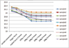
A finger force, 3 times of malleting force, and load of 20 kg were added in order and the amount of sinking was obtained by measuring length of abutment-fixture with Absolute Digimatic Caliper® (Mitutoyo, Kawasaki, Japan) (Fig. 7, Table I).
As seen above, abutment kept sinking as loads were added. After 5 - 7 times of load of 20 kg, sinking stopped at 0.45 ± 0.09 mm, except for sample 4. It took 9 times of load of 20 kg to stop sinking.
2. Statistical analysis (Fig. 8)
In Oneway ANOVA on Ranks, the amount of abutment sinking under Load 1 showed statistically significant difference with that of Load 4 and above (Tukey Test, P < .05).
DISCUSSION
In this study, masticatory force was assumed as 20 kg. This value was referred to Gibbs and Mahan,9 Craig,10 Andersson,11,12's study about occlusal force in natural dentition and Richter et al.13's study about occlusal force while implant functioning. However many studies demonstrated that direction and amount of occlusal force is not regular. It is reported the maximum vertical occlusal force that human can make is close to 800 N and lateral force to 20 N.14 Also implants on posterior regions connected to premolars obtained 60 - 120 N of vertical loading while chewing were reported. In single premolar or molar, implants got maximum 120 - 150 N of vertical loading. Also clenching in centric occlusion caused 50 N of loading both in natural and artificial teeth were reported.13 In this study, loading application instrument was manufactured and load of 20 kg corresponding to masticatory force was applied. Unlike in oral conditions, fixed loads were applied in a fixed direction which gave limitations for representing forces applied in oral conditions.
The magnitude of the forces made by finger pressure and malleting can be converted into numerical value using Basic Force Gauge®(Mecmesin, Slinfold, England).15 Lee et al. figured out the mean value by measuring 20 times for each force and the measurement was carried out by one person. As a result, they got the average value of finger force 5.91 ± 0.58 kg, malleting force 3.35 ± 0.29 kg.
The amount of abutment sinking in Bicon® implant system was increasing as loads were added. After 5 - 7 times of load of 20 kg, sinking stopped at 0.45 ± 0.09 mm, except for sample 4. It took 9 times of load of 20 kg to stop sinking. Studies were performed about abutment sinking. Lee et al. observed the amount of abutment sinking in Alloden® implant system (Nei corp, Seoul, Korea) (one of locking taper connection type implant)15. They reported 0.51 ± 0.06 mm of sinking when loads were applied 7 - 8 times in conventional abutment, and 0.75 ± 0.06 mm of sinking when loads were applied 10 - 13 times in For Deep Implant (FDI) abutment®. Comparing with our result, Bicon® implant system had less amount of sinking and less number of times needed to stop sinking than Alloden® implant system. Bruno Dailey et al. observed a continuous displacement of BiAbutment® (Astra Tech, Molndal, Sweden) of tapered cone screw internal connection type into implants or into replicas for torque between 0 and 45 Ncm.16 There was a continous axial displacement of abutment and application of torque above the level recommended by the manufacturer increased the differences in displacement between the two groups. Comparing with our result, Bicon® implant system had more amount of sinking.
Consequently, locking taper type implant can cause occlusal discrepancy resulting from abutment sinking due to mastication. Thus when using locking taper connection type implant like Bicon® implant system, following methods can be thought to prevent occlusal change caused by abutment sinking due to mastication. In laboratory, abutment should be tapped sufficiently in advance of making prosthesis. In clinic, dentist performs occlusal adjustment to some degree and finish complete occlusal adjustment after making sure the patients masticate enough for period of time. In clinic, after connecting abutment, patients should use temporary crown for enough period of time and then impression for abutment should be taken. Also checking amount of sinking through periodic follow-up is recommended. From statistical analysis, the amount of abutment sinking under Load 1 had statistical difference with that of Load 4 above. Thus, the length under finger force shows statistical difference with that of 3 times of malleting force and 5 times of load of 20 kg corresponding to masticatory force. Therefore, it has clinical implication that connecting abutment with malleting force and applying 5 or more times of masticatory force.
Therefore, when locking taper connection type implant is used, masticatory force of 5 or more times for precise abutment location and follow-up check for correcting occlusal discrepancy are recommended.
CONCLUSION
In this study, we used Bicon® Implant System (Bicon Inc, Boston, USA) to recognize the effect of abutment sinking on occlusion with Locking taper connection type implant, also some loads on abutments connected to the fixture were applied and the amount of sinking of implant was measured. Then adaptivety of connection of abutment-fixture was observed through field emission scanning electron microscopy.
The results were as follows:
1. The amount of abutment sinking in Bicon® Implant System increased as loads were added.
2. When loads were applied more than 5 - 7 times, sinking stopped at 0.45 ± 0.09 mm.
In conclusion, locking taper connection type implant showed generally favorable fitness to masticatory force. However the amount of abutment sinking increased with adding loads. Therefore when locking taper connection type implant such as Bicon® implant system is used, enough load strength is recommended for precise abutment location.


 XML Download