

 PDF
PDF ePub
ePub Citation
 Print
Print


INTRODUCTION
The role of fixture mount in implant dentistry is to carry the implant and to transmit the necessary clockwise or counter-clockwise torque for implant placement.1 Fixture mount fully or partially engages the implant/abutment interface of the implant.
Conventionally, the implant/abutment interface is described as external or internal connection. The connection can be further divided into 2 categories, a slip fit and a friction fit joint. For the implants, which have external or internal slip fit implant/abutment interface, the mating surface of the mount/implant acts as an indexing feature. A fixture mount can be deliverd not only clockwise inserting torque, but counterclockwise removing torque from the an implant. However, in most implant systems with internal friction fit joint, the fixture mount has no indexing features. Once counter-clockwise torque was applied, the fixture mount is released from the implant. Therefore, it is not possible to remove and reinstall an implant once it is stabilized in the bone.
The fixture mount was considered as an inevitable device for threaded implants. However, clinicians faced several inconveniences using fixture mounts. To solve the problems with fixture mounts, an implant driver was introduced for an external slip fit implant.2 Implants have notches in the coronal portion of abutment screw threads. The implant driver engages the notches and transmits clockwise or counter-clockwise rotational torque. Implant drivers were also introduced for the implants with internal connection. Thereafter, implants with internal friction fit can be rotated counter-clockwise and clinicians can remove the implant when necessary. However, using an implant driver has a potential problem in the internal friction fit implants. When the driver fully or partially engages the indexing features of the abutment/implant interface, excessive torque may cause some deformation on the interface.3
Amount of the rotational freedom between an implant and its abutment is regarded as an important factor to determine the long-term stability of the implant/abutment joint. The deformation on the abutment/implant interface may increase the amount of the rotational freedom between abutments and implants, and compromise the long-term success of the implant treatment.
The purpose of this study is to evaluate and compare the amount of change in rotational freedom between 3 internal connection implant systems without fixture mounts and their corresponding abutments after applying different insertion torques. There is no difference in the amount change in rotational freedom between an implant and its abutment before and after applying 45 Ncm and 100 Ncm of insertion torque. It is taken as the null hypothesis.
MATERIAL AND METHODS
Implant systems
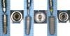
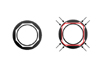
Three kinds of implant systems with internal connection implant/abutment interface were used for this study. The first implant group is 12 mm length, 4.5 mm diameter implant (Xive, Friadent, Germany), which has a slip fit, internal hex connection. The Xive implant is packaged with a fixture mount (TempBase, Friadent, Germany), but an operator can use an implant driver to install an implant after removing the mount. The second is 11.5 mm length, 4.3 mm diameter Implant (Inplant Magicgrip, Warantec, Seoul, Korea), which has a friction fit, internal octagon implant/abutment interface with 7 degree taper. The third is 12 mm long, 4.3 mm diameter implant (Implantium MF, Dentium, Seoul, Korea), which has a friction fit, internal hexagonal implant/abutment interface with 11 degree taper. Fig. 1 shows the internal hexagonal or octagonal surfaces of each implant system and corresponding implant drivers. Five samples were utilized for each group. The EstheticBase straight abutment (GH3, Friadent, Germany), 2-piece top abutment (IOTA4524E, Warantec, Seoul, Korea), a Dual abutment (DAB5525HL, Dentium. Seoul, Korea) were used as the abutment for each implant system. Same abutments were used for the same groups.
Torque assay
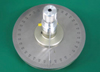
A device was developed by the department of dental materials (College of Dentistry, Yonsei university, Seoul, Korea) to measure the amount of rotation. The device consisted of a round base table and an upper rotating clamp. The base table also had a clamp on its center 360 degrees scale around it. The upper clamp rotated on the centre of the base table and could hold an object in the center of the clamp with 3 fingers. The upper clamp had a pointing needle indicating the numbers of degrees on the base table (Fig. 2).
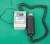
To measure the amount of rotational movement between an implant and its implant driver, an implant was held by the three fingers in the upper clamp, the head of an implant driver was positioned into the implant and the shaft of the driver was held in the clamp of the base table. To measure the amount of rotational movement between an implant and its corresponding abutment, the implant driver was removed, the abutment was positioned until it was passively seated into the implant and the head of the abutment was then held by the fingers of the clamp of the base table. The upper clamp was rotated in clockwise and counter-clockwise directions until the implant driver or the abutment bound to the implant at each extreme. The difference of degrees between clockwise and counter-clockwise movements was recorded as the amount of rotational freedom between the implant and implant driver or implant and abutment. The minimum degree unit of the base table is 1 degree, the measurement was read to the closest 0.5 degree by the naked eye. Initial measurements were done for every possible seating position of an implant driver or an abutment to the implant for every sample. In other words, an implant driver or an abutment was seated, measurement of the rotational freedom was taken, the implant driver or the abutment was removed and rotated to the next indexing corner (60 degrees for Xive and Implantium MF, 45 degrees for Inplant magicgrip) and the rotational freedom was measured. This procedure was repeated until the implant driver or the abutment rotated 360 degrees. Therefore, 6 measurements were done for each sample of Xive and Implantium MF, 8 measurements were done for each sample of Inplant magicgrip. The mean of the 6 or 8 measurement was taken as the initial value of the rotational freedom of the implant/implant driver or implant/abutment interface. A digital torque gauge (Mark-10, NY, USA) was used to transmit insertion torque (Fig. 3). The shaft of the implant driver was held by the clamp of the digital torque gauge, the driver was passively seated into an implant and 45 Ncm insertion torque was applied for 5 seconds. The same measurement procedures were performed for the initial value of the rotational freedom of implant/implant driver or implant/abutment. Then, 100 Ncm torque was applied for 5 seconds using the digital torque gauge and the implant driver. The amounts of rotational freedom between implant and implant driver or implant and abutment were measured as described above.
Statistical analysis
SPSS statistical software for Windows (release 10.0, SPSS, Chicago, IL, USA) was used for all statistical procedures. The Kolmogorov-Smirnov test was performed to verify normal distribution of the measurements. The amounts of the rotational freedom were compared before and after applying 45 and 100 Ncm of insertion torque by repeated measures ANOVA at a significance level of P < .05.
RESULTS
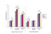
Table I and Fig. 4 showed the mean values of the rotational freedom between an implant and corresponding implant driver (45 Ncm, 100 Ncm of inserting torque), an implant and corresponding abutment (45 Ncm, 100 Ncm insertion torque) for each implant system. The Xive implant system alone did not show any significant change of rotational freedom between implant and implant driver after applying 45 Ncm of insertion torque (P = .338). For the rotational freedom between implant and abutment, both Inplant Magicgrip and Implantium MF did not show significant change of the rotational freedom under 45 Ncm of torque (Inplant Maginc grip; P = .208, Implantium MF; P = .211). Xive implant system resulted in significant increase of rotational freedom between implant and its abutment under 45 Ncm of insertion torque. Under 100 Ncm of insertion torque, Implantium MF and Xive resulted in significant increase of rotational freedom between implants and their corresponding abutments (Implantium MF; P = .022, Xive; P = .014).
DISCUSSION
Implant drivers are getting popular in clinical implant dentistry. An implant driver can facilitate easy access to limited area and secure visual operation field. However, implant drivers have a drawback. For internal connection implant systems, an implant driver fully or partially engages the implant/abutment interface. Deformation of the implant/abutment interface could be introduced when excessive insertion torque was applied. Bambini et al. evaluated the deformation of the external hexagonal and internal octagonal extension after applying different insertion torques.3 Scanning electron microscope analysis results showed that the amount of deformation was proportional to the magnitude of applied insertion torque. The deformation on the implant/abutment interface possibly influences the amount of rotational freedom between an implant and its abutment.
The amount of rotational freedom between an implant and its abutment is regarded as an important factor for maintaining the stability of implant prostheses.5 Binon evaluated the amount of misfit between the implant hexagonal extension and the internal hexagonal recess of abutment and concluded that the greater the hexagonal misfit, the greater the probability of screw loosening.6
In the current study, rotational freedom between an implant and its abutment were evaluated using three internal connection implant systems. Three implant systems had their own implant/abutment features. Xive had internal slip fit implant/abutment joint. Implantium MF and Inplant Magicgrip had internal friction fit implant/abutment joint. The implant driver of Implantium MF engaged the future implant/abutment interface. In the contrary, the implant driver of Inplant Magicgrip occupied different rectangular recesses which were provided in the deeper part of implant body and never touched the future implant/abutment interface (Fig. 5). Even though, the amount of rotational freedom between Inplant Magicgrip and implant driver was significantly increased, the rotational freedom between the implant and its abutment was not changed significantly after 45 and 100 Ncm of insertion torque. The reduced implant/abutment interface may produce decreased resistance of abutment loosening.5 However, Squier et al. reported that the reduced mating surface area due to addition of internal indexed surface did not have deleterious effect on the resistance to loosening of its abutment.13
Current study showed that the Implantium MF group resulted in more than 5 degrees of rotational freedom between the implant and its abutment whereas the other two implant systems resulted in less than 3 degrees of rotational freedom under insertion torque of 45 Ncm. Binon reported that less than 2 degrees of rotational freedom between an implant and its abutment showed the most stable joint, and more than 5 degrees of rotational freedom resulted in dramatic decrease in the number of loading cycles needed to loosen the implant/abutment joint.6 Many studies compared the number of loading cycles in loosening the joint for external or internal connections, but only a few studies evaluated the relationship between the amount of rotational freedom and the number of loading cycles.7-10 There was no reported comparison of joint stability between implants with internal and external connection in relation to the amount of rotational freedom of the implant/abutment interface. Previous studies showed that internal connection resulted superior joint stability than external connection.10,11 However, implants with internal connection also presented greater amount of rotational freedom than external hex implants.12 When a friction fit internal connection implant has very small amount of rotational freedom, an abutment is hardly to seat into its implant body completely.4 If the abutment was not completely seated into the implant body, joint stability would be deteriorated. Therefore, the amount of rotational freedom should be differently speculated between implants with internal and external connection joint.
CONCLUSIONS
Within limitation of this study, followings were concluded.
1. Only Xive implant system resulted in no significant increase of rotation freedom between implant and implant driver under 45 Ncm of insertion torque.
2. No significant change was noted in the rotational freedom between Inplant and its abutment up to 100Ncm of insertion torque was applied.
3. Under 45 Ncm of insertion torque, the amounts of in-crease between implant components were less than 1 degree for the 3 implant systems used in this experiment.

 XML Download