

 PDF
PDF ePub
ePub Citation
 Print
Print


INTRODUCTION
In typical sinus surgery, surgeons use one hand to hold an endoscope and another hand to operate surgical tools. Both are the straight type. Thus, as seen in Fig. 1, there are many blind regions in the sinus area to which any currently existing surgical tools cannot reach and any endoscope cannot visualize. Thus large invasive surgery is inevitable to treat target legions in the blind regions.
Current trend in computer-aided surgery is minimally invasive surgery. Using this concept, many surgical robotic systems have been successfully employed in operation room. There are three issues to provide true minimally invasive surgery.
i. flexible mechanism that enables surgical endoscope or devices to approach the target legion
ii. navigation software with advanced functions
To date, research activities in the area of flexible mechanisms have been very active for last 10 years. Burgner-Kahrs et al [1] surveyed most research works related to flexible mechanisms. Among them, Choi et al [2] was the first one who suggested a flexible endoscope. They employed a spring as a backbone of the flexible endoscope. At the distal end of the mechanism, a camera of 3 mm diameter with resolution of 400x400 was installed. This flexible endoscope was able to look inside the maxillary sinus by turning 180 degrees. Its radius of curvature of diameter was designed as 10 mm to fit into the anatomy of the typical maxillary sinus of Korean people. Simaan et al [3] investigated an active compliance control algorithm for sinus surgery. Rather than using any navigation algorithm, their designed flexible mechanism measured the contact force during insertion and was able to comply to the sinus wall not to damage the sinus area. Yoon et al [4] developed a dual robotic system that consists of one flexible endoscope and one flexible biopsy device. The total diameter of two devices are less than 10mm. Thus they can be successfully inserted into the nostril of the nose. Webster et al [5] also developed a dual sinus surgical system, but their design is more or less bulky as compared to Yoon's design.
Navigation software and system is popular in the operation room. Most frequently used area is brain surgery. Brain Lab is well-known navigation software for brain surgery. Recently, such navigation software has started to be applied to sinus surgery. However, their functionality is very limited. Sometimes result of registration between the patient coordinate and the image coordinate is not accurate. Much advanced navigation algorithm producing better accuracy and additional function is required. Matsumoto et al [6] was the first one who investigated 3D image-guided sinus surgery. Yoon et al [7] combined the navigation software and flexible endoscope. Not only providing the camera image, but also a real time 3D navigation software displaying the flexible endoscope on the pre-operatively developed 3D image is provided for better user interface.
This article is organized by the following order. Initially, anatomy of the sinus area will be introduced to provide a general design specification in the design of flexible endoscope and flexible devices. Next, design of flexible endoscope and flexible devices will be discussed. Navigation software will be followed. Finally, we will draw a conclusion.
ANATOMY OF SINUS
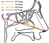
Sinuses are hollow air-filled spaces in the cranial bones, which are connected to the nose on the facial part of the cranial bones as shown in Fig. 2. Sinusitis is an inflammation of the tissue that lines the sinuses. The aim of sinus surgery is to open up blocked sinus passages, get rid of infected lesion, and keep tissue healthy so that the sinuses are able to function normally.
To determine specifications for sinus surgery, it is necessary to analyze the anatomical dimensions of the sinus. Based on average adults, the mean size of the maxillary sinus is given as follows. The anterior section of the maxillary sinus is 26.2 mm in width on the right side, and 26.9 mm on the left side. The length of the medial side of the maxillary sinus is 38.4 mm in the right, and 39.1 mm on the left [9]. The diameter of the nostril opening can be estimated as 10 to 12 mm, because the average area of the nostril opening of average adults is 357.83 mm2 [10]. Fig. 2 shows the measured distances from nostril to the landmarks of sinuses. The distance from nostril to basal lamella is 57.9 mm. The distance from nostril to posterior wall of the ethmoid sinus is 74.4 mm. The distance from nostril to maxillary ostium is 48.3 mm. The distance from nostril to posterior wall of sphenoid sinus is 83.7 mm. [11].
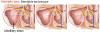
Requirements of the robotic device for sinus surgery have been decided based on anatomical structure of the sinuses and the clinician's opinion. As shown in Fig. 3, the distal tip of the endoscope end-effector should be bent by 180 degrees in order to inspect the entire interior of the maxillary sinus. It should also have a small radius of curvature. Such bendable endoscope enables inspection of a wide workspace and even invisible region blocked by organs, tissues, or other tools. The bendable endoscope provides the operator with a broad and detailed view of the maxillary sinus.
In sinus surgery, various instruments are used such as shaving device, biopsy device, and so on. Yoon et al [4] proposed a biopsy device to take a sample of tissue or eliminate the target lesion inside the maxillary sinus.
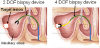
As shown in Fig. 4, the biopsy device should have more than three degrees of freedom for biopsy operation in order to reach any target lesion inside the maxillary sinus. In order to reach and remove any target lesion inside the maxillary sinus, the bendable part of the biopsy device should be longer than the endoscope device and be bendable by more than 180 degrees.
As shown in Fig. 2, the mean distance from nostril to maxillary ostium is 48.3 mm and the longest length inside of the maxillary sinus is 39.1 mm. Therefore, the insertion length of the endoscope end-effector should be longer than 87.4 mm and the length of bendable module should be longer than 39.1 mm in order to observe the interior of the maxillary sinus. The required length of the bendable part includes the focal length of the endoscopic camera. In the case of the biopsy end-effector, it should be designed to have a longer length of the bendable module and a longer insertion length than the endoscope end-effector. This is because the biopsy end-effector should be inserted deeper than the endoscope end-effector in order to reach and remove the target lesion. The longest distance from nostril to the landmarks of sinuses is 83.7 mm. Thus the device developed for the maxillary sinus is applicable to all sinus areas.
FLEXIBLE ENDOSCOPE AND DEVICES
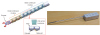
The endoscope end-effector proposed by Yoon et al [12] is a flexible mechanism which employs a backbone spring shown in Fig. 5. There are many advantages of using a spring as a backbone. The device using a spring backbone has the flexibility of the whole body. Thus, it can assure safety even in the case of collision with human tissue or organs. Another advantage is the usefulness of the empty space inside the spring backbone. Wires used for the camera and the light source can be inserted through the empty space of the spring.
The continuum module of the endoscope end-effector is comprised of six nodes as shown in Fig. 5. Each node is made up of a cylinder and a spring. By controlling three wires, the continuum module produces 2 tilting motions and a compressing motion. The continuum module is designed to be bendable by up to 180 degrees.
The biopsy end-effector proposed by Yoon et al [4] is composed of a 4 degrees of freedom (DOF) continuum mechanism and a 1 DOF gripper. As shown in Fig. 6, a 4 DOF continuum mechanism is composed of two continuum modules. By pulling and releasing two sets of wires, with each continuum module the biopsy end-effector produces 2 tilting motions. The distal continuum module and the base continuum module are comprised of three and six nodes, respectively. The distal module is designed to be bendable by 180 degrees and the base module is designed to be bendable by up to 90 degrees.
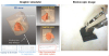
Although the biopsy end-effector is comprised of continuum modules like the endoscope end-effector, the detailed structure of the continuum module of the biopsy end-effector is different from that of the endoscope end-effector. In order to biopsy some tissues inside the maxillary sinus, the biopsy end-effector should have a considerable payload. In order to increase the amount of payload, a ball joint is inserted between two neighboring cylinders of the biopsy end-effector as shown in Fig. 7. The ball joint plays the role of an internal backbone and resultantly it raises the stiffness of the continuum module.
NAVIGATION SOFTWARE
Navigation software proposed by Yoon et al [13] offers the operator an endoscopic image and a graphic simulator. The graphic simulator is composed of a 3D view, a sagittal view, and a coronal view as shown in Fig. 7. The information for the 3D model of patient and the end-effector is displayed on the graphic simulator. Thus, by using the navigation software, the surgeon can navigate through the sinus area more accurately and safely. The biopsy operation can be monitored through the endoscopic image. The navigation software and the robotic system are connected to each other through TCP/IP protocol. The period of data transmission is less than 10 milliseconds.
- Registration between robot and image coordinates
For navigation through the sinus area using the navigation software, registration between the robot coordinate system and the image coordinate system should be performed as shown in Fig. 8. Then, the endoscope end-effector and the image of sinus can be displayed through a virtual 3D graphic simulator of the navigation software. An optical tracking system made of Northern Digital Inc. is employed to measure the position and orientation of the end-effector and patient. For registration between the patient coordinate system and the image coordinate system, 3-dimensional coordinates of three or more points are needed. To obtain the coordinates of the points, we can use feature points of the patient model or use markers attached on the skin of the patient model before the CT scan. The standard PPR (point-to-point registration) method [14] is used for registration. Refer to Yoon and Yi [15] for the detail of the registration method.
RECOMMENDATION
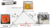
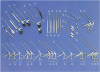
Typical sinus surgery is conducted using two hands as shown in Fig. 9. One hand holds the endoscope while another hand exchanges tools continuously. The future direction to improve the surgical condition for the surgeon can be considered in two aspects. First of all, the endoscope holder should be developed. Actually, there are commercialized endoscope holders in the market already. However, incorporation of navigation software into the holder is necessary to enhance the functionally endoscope holder [8]. The second consideration is developing angle-adjustable, flexible devices for endoscope, biopsy, and shaver. Currently, surgeons perform sinus surgery as they exchange surgical tools with difference angle. Using angle-adjustable, flexible devices for endoscope, biopsy, and shaver would greatly reduce the number of devices (as shown in Fig. 10) for sinus surgery.
CONCLUSION
This article provides a review in computer-aided sinus surgery. Using the conventional approach based on the straight endoscope and instruments, there are some limitations in inspection and treatment of the target lesion of the sinus. This is because the pathway to the sinus area is anatomically curved and narrow. In that sense, flexible devices have an advantage in sinus surgery because they enable the surgeon to diagnose and cure the blind region that cannot be treated by using existing endoscopic devices.
Anatomy of the sinus area was introduced to provide general design specification in the design of flexible endoscope and flexible devices. Specifically, design of flexible endoscope and flexible devices was discussed.
Incorporation of navigation software into a counter-balancing mechanism would greatly enhance performance of sinus surgery. Angle-adjustable devices with flexible structure should also be developed to provide the surgeon with convenient use.

 XML Download