

 PDF
PDF ePub
ePub Citation
 Print
Print


INTRODUCTION
In orthodontics, anchorage for inhibiting the movement of teeth has always been an important consideration. The conventional methods of temporary anchorage include headgears, elastics, Nance devices, and lingual arches. However, these methods have limitations such as esthetic concerns, cooperation problems, and adverse effects. Recently, temporary skeletal anchorage devices (TSADs) such as osseointegrated mini-implants, miniplates, and mini-screws have been widely studied.1-3 Clinicians prefer using mini-screws (machined screw surface) and mini-implants (coated screw surface) since they are easy to place and remove and can enhance the biomechanical effects.3-8
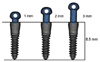
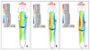
Orthodontic mini-implants (OMI) and mini-screws are of 2 types: one-component or two-component systems; these implants have a removable head (mini-implant) (Fig 1). The screw part of the mini-implant is also surface treated for better osseointegration, which allows the application of dynamic or rotational forces.9-12 The head part of the mini-implant, from the top of the screw part to the hole in the head part, is available in 3 sizes: 1 mm, 2 mm, and 3 mm (Fig 2). The mini-implant has also been used as a provisional or final prosthetic implant in children or patients who have insufficient space for holding a conventional dental implant.13 The stress distribution of external forces in one-component devices has been well studied, but finite element analysis (FEA) for two-component OMIs is lacking.14-21
FEA allows a thorough assessment of the response of both TSADs and bones experiencing orthodontic forces. Three-dimensional (3D) computer models can be used to simulate various conditions by varying the simulation parameters. The present study aimed to evaluate the stress distribution by using 3D FEA when the two-component OMIs with the 3 different head sizes are used. The results of this study will increase the understanding of clinicians using this type of OMIs.
MATERIAL AND METHODS
Construction of the FE model
Model configuration
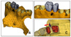
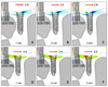
The FE model comprised a two-component OMI, teeth, and the maxillary bone. The bone was scaled as shown in the image provided by Digimation Ltd. (Lake Mary, FL, USA). The OMI used in this study had a diameter of 1.8 mm and length of 8.5 mm (mini-implant; CIMPLANT Co., Seoul, Korea). The implant was placed 4 mm apical to the peak of the alveolar crest between the roots of the upper second premolar and the first molar. The mini-implant was inserted such that the top part of the screw thread became flush with the soft tissue. The cortical bone and periodontal ligament were scaled to a thickness of 1 mm and 0.2 mm, respectively. Varying mesh sizes of the FE were used for the analysis in order to evaluate the stress distribution of the implant in detail. The implants were uniformly modeled with a mesh size of 0.1 mm. The corresponding mesh part of the bone that connected with the implant was modeled such that it had the same size as that of the implant (i.e., 0.1 mm). Lastly, the size of the implants was gradually increased until the external area of the bone ranged between 5 and 10 mm (Fig 3).
In the OMI, the head part was fitted to the screw part with a friction fit. This caused both the head and screw parts to become mutually deformed. Hence, when a load was applied to the head part, its stress was transmitted to the screw part via the friction of the connection. The friction fit of the head and screw parts was embodied through pre-simulation instead of simply connecting the 2 nodes of the parts. The initial stress generated by the friction fit was taken into account, and the amount of load transmission from the head to the screw part was calculated.
Material properties and loading conditions
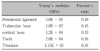
In order to calculate the implant stress, we assumed that a bone is homogeneous, isotropic, and linearly elastic. The material properties were calculated using Young's modulus and Poisson's ratio, as has been reported in previous studies (Table 1).22,23 A schematic illustration of the situation when a lateral force of 2 N is applied to the center of the hole in the head part of the mini-implant is shown in Fig 3C. In the present study, the entire maxillary bone was modeled. That is, the model extended into the boundary limit between the maxillary bone and the surrounding bone, thus preventing the distortion of stress that might have resulted if only a limited bony section was modeled.
The results of the FEA were tested using PAM-MEDYSA version 2009 program (ESI, Paris, France).
RESULTS
Stress distribution in an early stage
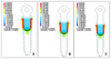
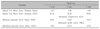
The stress distribution of the implant when the head part is fitted by friction (tapped into place) after the implantation of the screw part is shown in Fig 4. Because of the mechanical design of the fitted surfaces between the head and screw, the stress was mostly distributed in the receiving cavity of the screw. The insertion point of the head part was laterally tapered by 1.5°. Stress was uniformly distributed over the bone surface where the head part was inserted. Stress was greater in the upper part of the implant where the head and screw parts were coupled. The length of the head part did not affect the amount of stress or its distribution (Table 2).
Stress on the OMI after 2 N of lateral force was applied
The stress distribution pattern after the application of a lateral force of 2 N is shown in Fig 5. Tensile stress was generated on the side of the head part where the lateral force was applied; this led to the generation of maximum stress in the area of head and screw part coupling. Compressive stress was generated at the contralateral side of the screw receiving the lateral force. Tensile stress was generated in some areas of the screw part. Stress was also generated on the top area of the screw part that came in contact with the head part where compression stress was generated. The longer the head part, the greater was the stress. The stress at the head part increased in proportion to that at the screw part (Table 2).
Stress distribution on the bone after 2 N of lateral force was applied
Compressive stress was generated on the contralateral side of the cortical bone where the lateral force was applied. Tensile stress was generated on the cortical bone side where the lateral force was applied. Moreover, stress was greater at the contralateral side of the boundary between the cancellous bone and cortical bone to which the lateral force was applied. The length of the head part was correlated with the amount of stress generated across the implant as well as that generated in the cortical bone (Table 2).
DISCUSSION
When placing a prosthetic implant in an edentulous area, determining the stress distribution of the occlusal load on the implant and the surrounding bone is important. Osseointegration is essential to ensure that the implant remains stable under the occlusal load. The objective of achieving osseointegration is to effectively distribute the load up to the depth of the bone. Many studies have determined the stress distribution after placement of prosthetic implants.24-27 Sertgöz and Güvener24 used the 3D FE method to analyze the stress to the bone and implant surfaces after placement of implant-supported dentures. Skalak25 showed that the stress increases in proportion to the load applied to the implant; however, the increased load does not affect the phase of stress distribution. Moreover, researchers have shown how stress distribution is influenced by the size and shape of the implant as well as bony factors27,28 such as bone density and cortical bone thickness. Results obtained by dental implant studies cannot be directly used to understand the changes occurring after the placement of mini-implants. This is because there are differences between dental implants and mini-implants. First, unlike dental implants, mini-implants are loaded immediately or within 4 weeks. Second, prosthetic implants are placed in the occlusal surface of the alveolar bone, while mini-implants are placed in the inter-radicular space. Third, the vector of the applied force is through the dental implant axis, while it is lateral to the mini-implant axis. Lastly, dental implants are permanent, while mini-implants are temporary and removed when not required. Similarly, the mini-implant differs from the one-component mini-implant with respect to the two-part design and thus requires an independent study. Seo et al. showed that the mean bone-to-implant contact (BIC) after the removal of a sandblasted, large-grit, and acid-etched (SLA) mini-implant was 52.6%, indicating partial osseointegration.29 This suggests that the SLA mini-implant is resistant to heavy and dynamic forces, as well as to rotational movements produced by the intrusive movement of the retraction biomechanics. Moreover, Kim et al. showed that, during removal, SLA OMIs had relatively lower insertion torque and angular momentum but higher total energy than implants having a machined surface, suggesting that SLA mini-implants showed better osseointegration after insertion.13
The mini-implant head available in various sizes is exchangeable, and hence, the extent of the force applied can be varied without requiring an expensive inventory of implant devices. Implants with long head parts are useful for conducting intermaxillary fixation during jaw surgery, allowing multiple force applications, facilitating an angulated vector of insertion, or allowing implant fixation in thick soft tissues such as the palate.10,30 The longer head part reduces the risk of screw loosening because of the surface treatment of the screw, thereby enhancing osseointegration.
Mini-implants can be used as a preliminary restorative aid when the morphology of the alveolar bone is not ideal.13,31 A two-component OMI can be used to provide anchorage for a prosthetic restoration.
The two-component OMI uses a friction fit to combine both the head and screw parts. Therefore, early determination of stress distribution is important. At the initial state, the head part length hardly affects stress distribution since the signed von Mises stress is 4.47 - 4.48 MPa. Although the stress distribution after the placement of two-component OMIs with different head lengths is similar, the extent of stress increases in proportion to the length of the head part (Fig 5 and Table 2).
We found that the compressive and tensile stress levels at the adjacent bone are mainly concentrated on the cortical bone area when a lateral force of 2 N, which is commonly used in orthodontic practice, was applied. The stress value ranged from 8.95 MPa to 15.33 MPa, increasing in proportion to the length of the head part (Fig 6 and Table 2). According to a previous study, the physiologic limit for biological deformation of the cortical bone after placement of a one-component is 4,000 µ-strain (0.4% strain).32,33 That is, no damage to the cortical bone occurs during the remodeling process if the stress applied is within approximately 50 µ-strain - 4,000 µ-strain31-33; this corresponds to 0.6 - 48 MPa compression stress on the cortical bone (E = 12.0 GPa). As per these criteria, the compressive and tensile stress levels applied to the cortical bone in this study were confirmed to be safe for clinical use.
In the present study, FEA was conducted since the two-component OMI has a surface-treated screw. Studies have shown better osseointegration of surface-treated mini-implants than machined-surface mini-implant.7,12,33 Further studies are needed determine the stress distribution during the placement and removal of surface-treated mini-implants and under various force applications such as rotational force or dynamic force application.
CONCLUSION
Two-component OMI has clinical benefits because of its replaceable head part. The FEA used in this study showed that the stress to the adjacent bone increased with the increasing head length but was within the physiological limit. Therefore, the two-component OMI can be used for clinical purposes.
 XML Download