

 PDF
PDF ePub
ePub Citation
 Print
Print


Abstract
Objective
Methods
Results
Conclusions
Figures and Tables
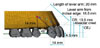
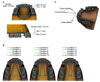 | Fig. 1
A, Three-dimensional finite element model for upper teeth, periodontal ligaments and alveolar bones; B, experimental groups are divided into three groups depending on the position of retraction: position of retraction arm in the first group is placed at the bracket of the 2nd molar, at the furcation of the 2nd molar in the second group and at the root apex of the 2nd molar in the third group; C, the coordinate system is composed of X-axis, Y-axis and Z-axis. The origin of coordinate axes is the middle point of the incisal surface which connects with the upper right and left incisors. X-axis is the bucco-palatal direction (lingual (+), buccal (-)); Y-axis is the antero-posterior direction (anterior (+), posterior (-)); Z-axis is the superior-inferior direction (superior (+), inferior direction (-)). CEJ, Cemento enamel junction.
|
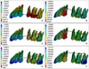 | Fig. 2Contour plot of frontal displacement at each condition. A, Length of lever arm is 0 mm and position of retraction hook is at the bracket of the 2nd molar; B, length of lever arm is 20 mm and position of retraction hook is at the bracket of the 2nd molar; C, length of lever arm is 0 mm and position of retraction hook is at the furcation of the 2nd molar; D, length of lever arm is 20 mm and position of retraction hook is at the furcation of the 2nd molar; E, length of lever arm is 0 mm and position of retraction hook is at the root apex of the 2nd molar; F, length of lever arm is 20 mm and position of retraction hook is at the root apex of the 2nd molar.
|
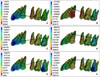 | Fig. 3Contour plot of vertical displacement at each condition. A, Length of lever arm is 0 mm and position of retraction hook is at the bracket of the 2nd molar; B, length of lever arm is 20 mm and position of retraction hook is at the bracket of the 2nd molar; C, length of lever arm is 0 mm and position of retraction hook is at the furcation of the 2nd molar; D, length of lever arm is 20 mm and position of retraction hook is at the furcation of the 2nd molar; E, length of lever arm is 0 mm and position of retraction hook is at the root apex of the 2nd molar; F, length of lever arm is 20 mm and position of retraction hook is at the root apex of the 2nd molar.
|
 | Fig. 4Contour plot of lateral displacement at each condition. A, Length of lever arm is 0 mm and position of retraction hook is at the bracket of the 2nd molar; B, length of lever arm is 20 mm and position of retraction hook is at the bracket of the 2nd molar; C, length of lever arm is 0 mm and position of retraction hook is at the furcation of the 2nd molar; D, length of lever arm is 20 mm and position of retraction hook is at the furcation of the 2nd molar; E, length of lever arm is 0 mm and position of retraction hook is at the root apex of the 2nd molar; F, length of lever arm is 20 mm and position of retraction hook is at the root apex of the 2nd molar.
|
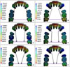
 | Fig. 5Comparison of the position of lever arm and CR of anterior teeth from other studies35: (blue)  - study by Jeong et al35 showing center of resistance of six anterior teeth; (green) - study by Jeong et al35 showing center of resistance of six anterior teeth; (green)  - study by Vanden Bulcke et al31 showing center of resistance of four anterior teeth; (purple) - study by Vanden Bulcke et al31 showing center of resistance of four anterior teeth; (purple)  - study by Vanden Bulcke et al31 showing center of resistance of six anterior teeth. CR, Center of resistance; CEJ, cemento enamel junction. - study by Vanden Bulcke et al31 showing center of resistance of six anterior teeth. CR, Center of resistance; CEJ, cemento enamel junction.
|
Table 2
Group 1, Retraction arm was positioned at the level of the 2nd molar bracket; Group 2, retraction arm was positioned at the furcation level of 2nd molar; Group 3, retraction arm was positioned at the root apex of 2nd molar; CI, central incisors; LI, lateral incisors; C, canine; PM, premolars; M, molars.
![]()
Table 3
Group 1, Retraction arm was positioned at the level of the 2nd molar bracket; Group 2, retraction arm was positioned at the furcation level of 2nd molar; Group 3, retraction arm was positioned at the root apex of 2nd molar; CI, central incisors; LI, lateral incisors; C, canine; PM, premolars; M, molars.
![]()
Table 4
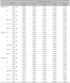
Group 1, Retraction arm was positioned at the level of the 2nd molar bracket; Group 2, retraction arm was positioned at the furcation level of 2nd molar; Group 3, retraction arm was positioned at the root apex of 2nd molar; CI, central incisors; LI, lateral incisors; C, canine; PM, premolars; M, molars.
![]()
 XML Download