

 PDF
PDF ePub
ePub Citation
 Print
Print


Abstract
Objective
The purpose of this study was to compare self-drilling orthodontic mini-implants of different surfaces, namely, machined (untreated), etched (acid-etched), RBM (treated with resorbable blasting media) and hybrid (RBM + machined), with respect to the following criteria: physical appearance of the surface, measurement of surface roughness, and insertion pattern.
Methods
Self-drilling orthodontic mini-implants (Osstem implant, Seoul, Korea) with the abovementioned surfaces were obtained. Surface roughness was measured by using a scanning electron microscope and surface-roughness-testing machine, and torque patterns and vertical loadings were measured during continuous insertion of mini-implants into artificial bone (polyurethane foam) by using a torque tester of the driving-motor type (speed, 12 rpm).
Results
The mini-implants with the RBM, hybrid, and acid-etched surfaces had slightly increased maximum insertion torque at the final stage (p < 0.05). Implants with the RBM surface had the highest vertical load for insertion (p < 0.05). Testing for surface roughness revealed that the implants with the RBM and hybrid surfaces had higher Ra values than the others (p < 0.05). Scanning electron microscopy showed that the implants with the RBM surface had the roughest surface.
Figures and Tables
Fig. 1
Shape and size (mm) of self drilling type orthodontic mini implant (Osstem Implant, Seoul, Korea).
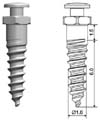
Fig. 2
Surface treated orthodontic mini implants. A, Machined surface; B, etched surface; C, RBM surface; D, hybrid surface. RBM, Resorbable blasting media.
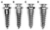
Fig. 3
SEM image of orthodontic mini implants (× 10). A, Machined surface; B, acid etched surface; C, RBM surface; D, hybrid surface. The surface difference between C and D is observed. SEM, Scanning electron microscope; RBM, resorbable blasting media.
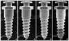
Fig. 4
SEM image of orthodontic mini implants (× 50). A, Machined surface; B, acid etched surface; C, RBM surface; D, hybrid surface. C and D have rough surfaces. White box indicates the area of magnification × 500. SEM, Scanning electron microscope; RBM, resorbable blasting media.
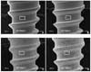
Fig. 5
SEM image of orthodontic mini implants (× 500). A, Machined surface; B, acid etched surface; C, RBM surface; D, hybrid surface. The surface difference between A and B is observed. SEM, Scanning electron microscope; RBM, resorbable blasting media.
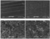
Fig. 6
The surface roughness of sample 1 of each group of A, machined; B, etched; C, RBM; and D, hybrid mini-implants. RBM, Resorbable blasting media.
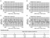
Fig. 7
Mean surface roughness (Ra) of surface treated orthodontic mini implants. Groups with the same letters were not significantly different from each other at the level of p < 0.05 (a < b). RBM, Resorbable blasting media.
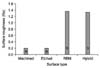
Fig. 8
Insertion pattern of sample 1 of machined surface group mini-implants. a, Vertical load for insertion (Ncm); b, rotational torque for insertion (Ncm).
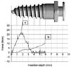
Fig. 9
Mean insertion torque patterns of surface treated orthodontic mini implants. RBM, Resorbable blasting media.
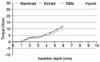
Fig. 10
Mean vertical load patterns for insertion of surface treated orthodontic mini implants. RBM, Resorbable blasting media.
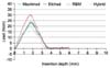
Fig. 11
Mean final insertion torque of surface treated orthodontic mini implants. a < b, c, d and b > d (p < 0.05). RBM, Resorbable blasting media.
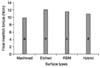
Fig. 12
Mean maximum vertical load for insertion of surface treated orthodontic mini implants. b > a > c (p < 0.05). Same letters were not significantly different. RBM, Resorbable blasting media.
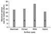
Table 1
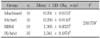
Chemical composition and mechanical properties of orthodontic mini-implant (Ti-6Al-4V alloy)
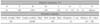
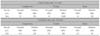
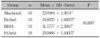
Table 3
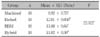
Comparison of mean surface roughness (Ra, µm) of the surface treated orthodontic mini-implants
References
1. Kanomi R. Mini-implant for orthodontic anchorage. J Clin Orthod. 1997. 31:763–767.
2. Chen Y, Shin HI, Kyung HM. Biomechanical and histological comparison of self-drilling and self-tapping orthodontic microimplants in dogs. Am J Orthod Dentofacial Orthop. 2008. 133:44–50.

3. Chen Y, Kyung HM, Zhao WT, Yu WJ. Critical factors for the success of orthodontic mini-implants: a systematic review. Am J Orthod Dentofacial Orthop. 2009. 135:284–291.
4. Crismani AG, Bertl MH, Celar AG, Bantleon HP, Burstone CJ. Miniscrews in orthodontic treatment: review and analysis of published clinical trials. Am J Orthod Dentofacial Orthop. 2010. 137:108–113.
5. Park JS, Yu W, Kyung HM, Kwon OW. Finite element analysis of cortical bone strain induced by self-drilling placement of orthodontic microimplant. Korean J Orthod. 2009. 39:203–212.
6. Kravitz ND, Kusnoto B. Risks and complications of orthodontic miniscrews. Am J Orthod Dentofacial Orthop. 2007. 131:4 Suppl. S43–S51.
7. Kuroda S, Yamada K, Deguchi T, Hashimoto T, Kyung HM, Takano-Yamamoto T. Root proximity is a major factor for screw failure in orthodontic anchorage. Am J Orthod Dentofacial Orthop. 2007. 131:4 Suppl. S68–S73.
8. Lee YK, Kim JW, Baek SH, Kim TW, Chang YI. Root and bone response to the proximity of a mini-implant under orthodontic loading. Angle Orthod. 2010. 80:452–458.
9. Poggio PM, Incorvati C, Velo S, Carano A. "Safe zones": a guide for miniscrew positioning in the maxillary and mandibular arch. Angle Orthod. 2006. 76:191–197.
10. Lim SA, Cha JY, Hwang CJ. Insertion torque of orthodontic miniscrews according to changes in shape, diameter and length. Angle Orthod. 2008. 78:234–240.
11. Kim JW, Baek SH, Kim TW, Chang YI. Comparison of stability between cylindrical and conical type mini-implants. Mechanical and histological properties. Angle Orthod. 2008. 78:692–698.
12. Cho IS. The initial stability of mini-implants according to surface treatment method (thesis). 2008. Seoul: Seoul National University.
13. Kim SH, Lee SJ, Cho IS, Kim SK, Kim TW. Rotational resistance of surface-treated mini-implants. Angle Orthod. 2009. 79:899–907.
14. Mo SS, Kim SH, Kook YA, Jeong DM, Chung KR, Nelson G. Resistance to immediate orthodontic loading of surface-treated mini-implants. Angle Orthod. 2010. 80:123–129.
15. Kasemo B, Lausmaa J. Aspects of surface physics on titanium implants. Swed Dent J Suppl. 1985. 28:19–36.
16. Chehroudi B, Gould TR, Brunette DM. Titanium-coated micromachined grooves of different dimensions affect epithelial and connective-tissue cells differently in vivo. J Biomed Mater Res. 1990. 24:1203–1219.
17. Le Guéhennec L, Soueidan A, Layrolle P, Amouriq Y. Surface treatments of titanium dental implants for rapid osseointegration. Dent Mater. 2007. 23:844–854.
18. Cochran DL, Nummikoski PV, Higginbottom FL, Hermann JS, Makins SR, Buser D. Evaluation of an endosseous titanium implant with a sandblasted and acid-etched surface in the canine mandible: radiographic results. Clin Oral Implants Res. 1996. 7:240–252.
19. Motoyoshi M, Hirabayashi M, Uemura M, Shimizu N. Recommended placement torque when tightening an orthodontic mini-implant. Clin Oral Implants Res. 2006. 17:109–114.
20. Blumenthal NC, Cosma V. Inhibition of apatite formation by titanium and vanadium ions. J Biomed Mater Res. 1989. 23:A1 Suppl. 13–22.
 XML Download