

 PDF
PDF ePub
ePub Citation
 Print
Print


INTRODUCTION
Scissors-bite is a condition in which the maxillary teeth are abnormally positioned in the buccal direction (or lingual direction for the mandibular teeth) to result in total crossbite.1,2 Correcting this condition is a problematic issue because the treatment methods used so far have limitations. For example, a sound third molar is required for use after extracting the maxillary second molar,3 and the application of a magnetic force with corticotomy requires a surgical procedure and its result depends on the patient's condition.4 Further, the modified transpalatal arch causes loss of anchorage and can be used only in mild cases because of limited space for lingual attachment on the affected second molar.5 The molar intrusion arch and cross-arch elastic also have disadvantages such as altered occlusion.6,7 Recently, the orthodontic mini-implant (OMI) was introduced for intrusion and correction of the maxillary second molar, but more than one implant is needed for direct bony anchorage and it is yet difficult to control torque and rotation.8,9
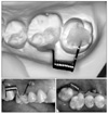
The dragon helix appliance combined with OMI-based indirect skeletal anchorage has been introduced recently to correct scissors-bite.1 This system consists of a helix with two arms, about 5 mm in length, made by 0.016" × 0.022" stainless steel wire set at an angle of 110° (Fig 1). One arm is attached to the occlusal surface of the maxillary second molar, while the other is attached to the buccal side of the maxillary first molar. This device produces about 200 - 250 g of orthodontic force without causing occlusal interference. The anchor tooth is connected to the OMI by a rigid wire such as 0.019" × 0.025" stainless steel, which provides strong indirect skeletal anchorage during the treatment of scissors-bite.10-13
However, considering that the OMI is the most important part of the appliance for anchorage, its position might have some effect on the efficiency of anchorage. The purpose of this study was to investigate the stress distribution on the OMI surface and periodontal ligament (PDL) of the maxillary first and second molars as well as the tooth displacement according to the OMI position in the dragon helix appliance during scissors-bite correction.
MATERIAL AND METHODS
A typodont model of the maxillary left quadrant with scissors-bite at the second molar, which was extruded and buccally inclined, was fabricated. The model was three-dimensionally (3D) scanned and 3D computer-aided design (CAD) data were acquired by using Computer-Aided Three-Dimensional Interactive Application Version 5 (CATIA V5; Dassault Systèmes, Vélizy-Villacoublay, France). The PDL attached to the root surfaces was fabricated from Hyper Mesh 8.0 (Altair Engineering, Troy, MI, USA). The Young's modulus and Poisson's ratio values of the PDL, alveolar bone, connecting wire, and dragon helix were assumed from an isotropic homogeneous linear elastic model (Table 1).
CATIA V5 was also used to create a finite element model of an OMI. Table 2 shows the elements and number of nodes. The dimensions of the OMI were 9 mm length, 5.7 mm spiral part, 0.6 mm pitch, and 5.7° taper angle. The dragon helix appliance was shaped into a spring of 2 mm diameter and 11 turns with 0.016" × 0.022" stainless steel wire. It was placed at the crown of the maxillary first molar and intrusively overcorrected second molar. Activation of the dragon helix appliance was simulated by fixing the distal arm to the affected second molar using the Constraint Equation of Ansys (ANSYS, Canonsburg, PA, USA). The appliance was assumed to produce about 200 - 250 g of force.1
The OMI and first molar were connected with 0.018" × 0.025" stainless steel wire for indirect anchorage, and the first and second molars were connected with the dragon helix appliance. Two groups were analyzed on the basis of the OMI position. In group 1, the OMI was positioned between the first and the second premolars, and in group 2, it was placed between the second premolar and the first molar. The stress distribution of the OMI and PDL of the first and second molars as well as the tooth displacement were analyzed by finite element analysis with Ansys version 11 and HP workstation XW 6400 (Zeon 1.6 Ghz, *2 CPU, RAM 4G).
The von Mises stress on the first and second molars, and the OMI was determined to evaluate the stress distribution. Displacement graphs of the axes of the OMI (from the center of the head to the screw end tip) and thefirst and second molars (from the palatal cusp tip to the palatal root apex) were used to observe the amount and pattern of displacement.
RESULTS
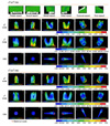
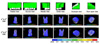
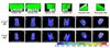
The maximal stress distribution area (SDA) of the maxillary first and second molars, and the OMI is shown in Fig 2 (in red). In group 1, the maximal SDA was observed at the cervical area of the first molar while the minimal SDA (in blue) was noted at the root apexes of the second molar. In group 2, the maximal SDA was observed at the palatal root apex of the first molar while the minimal SDA was noted at the furcation area of the second molar (Fig 2). Therefore, in group 1, the first molar showed greater tendency for buccal crown tipping but the second molar showed controlled tipping, while in group 2, the latter tooth showed uncontrolled tipping, presenting greater palatal crown movement.
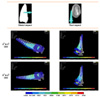
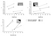
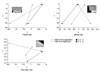
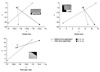
Although the maximal SDA on the OMI was not different between the groups, mesial bending of the OMI head was detected (Fig 3). From the magnified graph in Fig 4, the OMI head exhibited greater mesial displacement in group 1. Comparisons of the displacement of the maxillary first molars in the two groups are shown in Figs 5 and 6. The first molar crown moved distally and buccally in both groups, but the amount of displacement was greater in group 1. Further, the second molar crown in both groups showed distal movement, but the amount of displacement was greater in group 2 (Figs 7 and 8). Moreover, mesial and intrusive displacement of the second molar root was noted in group 2, whereas palatal displacement was confined to the crown of this tooth in group 1. Therefore, the movement of the second molar was more efficient in group 2.
DISCUSSION
OMIs have been widely used in orthodontics since their introduction as an effective anchor.9,14,15 Their easy application, in expensiveness, and possibility of immediate loading are well-recognized advantages. When an orthodontic force is applied directly to the OMI, it enables direct anchorage. This method of direct anchorage is more popular than indirect anchorage, which is considered to cause interference in osseointergration.16 However, direct anchorage with the OMI has disadvantages such as difficulty in placing it between anatomical structures, difficulty in controlling torque and rotation, and often requiring more than one implant, all of which could be overcome by an indirect method.10,11,13
The dragon helix appliance combined with OMI-based indirect anchorage has exhibited efficient treatment of scissors-bite by applying palatal and intrusive forces to the affected molar.1 This appliance was introduced to enable better comfort to patients, due to its small volume, and minimal or no loss of anchorage, due to the OMI as an indirect anchor.1 The insertion position or angle of the OMI can influence its stability and efficiency, which have been studied in the direct anchorage system.17,18 Placement of the OMI between the maxillary second premolar and the maxillary first molar, which was the recommended OMI position in-many studies,1,19,20 is often difficult because of anatomical limitations or root proximity.9,14 In this study, the maximal efficiency of indirect anchorage was observed when the OMI was positioned between the second premolar and the first molar (group 2). The maxillary first molar showed bodily movement and less buccal crown displacement, and the maxillary second molar showed not only greater palatal crown movement but also intrusion in this group. The OMI showed greater displacement in group 1, which had a longer distance between the anchor tooth and the OMI. This finding indicates that a shorter distance between the anchor tooth and the OMI in the indirect anchorage system results in a more efficient anchorage unit. From the buccal and palatal views, the crowns of the maxillary first and second molars tipped distally. This could be explained as a step bend effect, because the dragon helix appliance was fabricated with rectangular wire (0.016" × 0.022") and its two arms formed a step from the buccal view. Although minor movements of the OMI and maxillary first molar were noted in this study, the movements were considered tobe undetectable clinically, because of the indirect skeletal anchorage unit. The major clinical effect was considered to be palatal tipping and intrusion of the maxillary second molar, which was the most efficient when the OMI was placed between the second premolar and the first molar (group 2).
There might be other factors influencing indirect anchorage, such as the length and thickness of the connecting wire, occlusal force, position of the wire attachment on the crown, and method of attachment. Finite element analysis calculates the initial moment difference of the load, which does not include the long-term reaction.21-23 Therefore, the results could differ in the actual oral environment, which includes masticatory force, complex anatomical structures, other biological features, and the combination of these factors. Further studies should focus on the effects of these factors on indirect anchorage with this system.
CONCLUSION
Three-dimensional FEA of the dragon helix appliance combined with the OMI-based indirect skeletal anchorage indicated that placement of the OMI between the maxillary second premolar and the maxillary first molar enables more efficient anchorage and greater movement for scissors-bite correction than placement of the OMI between the maxillary first and the maxillary second premolars.


 XML Download