Abstract
Objective:
The purpose of this study was to assess the dentoalveolar compensation in facial asymmetry individuals using an integration of a CBCT image and a laser scanned dental cast image.
Methods:
The subjects consisted of 30 adults with asymmetric mandibles and 20 adults with symmetric mandibles. The CBCT and laser scanned dental cast images were integrated with a registration technique. Canine and first molar position and angulation were assessed from reference coordinates. The differences between deviated and non-deviated sides were analyzed with the paired t-test. The differences shown according to menton deviation were also statistically analyzed using Pearson correlation analysis.
Results:
The experimental group showed deviated and non-deviated side differences (dev.-ndev.) in the position and angle of the canine and first molars. Menton deviation showed positive correlation with the deviation side (dev.-ndev.) for the maxillary and mandibular 1st molar angles, negative correlation with the deviation side for the vertical position of the maxillary 1st molars, transverse position of the mandibular canine, transverse position and vertical position of the mesio-lingual cusp of the mandibular 1st molars.
Go to : 
REFERENCES
1.Worms FW., Isaacson RJ., Speidel TM. Surgical orthodontic treatment planning: profile analysis and mandibular surgery. Angle Orthod. 1976. 46:1–25.
2.Tani M., Iketani M., Watanabe M., Suda S., Fujimura N., Miyazawa M, et al. Posterior-anterior cephalometric analysis in patients with dentofacial deformities. J Jpn Stomatol Soc. 1989. 35:1749–59.

3.Kim DW., Son WS. The relationship between facialasymmetry and maxillary dental arch shape. Korean J Orthod. 1997. 27:445–56.
4.Sung JH., Son WS., Kim SS. The relationship between posterior dental compensation and skeletal discrepancy in class III malocclusion. Korean J Orthod. 2003. 33:41–9.
5.Fukushima K., Yasui K., Otsuka Y., Matsui S., Hirase N., Takayanagi J, et al. Morphological characteristics of patients with jaw deformities -frontal cephalometric evaluation of facial symmetry-. Meikai Univ Dent J. 2003. 32:118–23.
6.Kusayama M., Motohashi N., Kuroda T. Relationship between transverse dental anomalies and skeletal asymmetry. Am J Orthod Dentofacial Orthop. 2003. 123:329–37.

7.Nojima K., Yokose T., Ishii T., Kobayashi M., Nishii Y. Tooth axis and skeletal structures in mandibular molar vertical sections in jaw deformity with facial asymmetry using MPR images. Bull Tokyo Dent Coll. 2007. 48:171–6.

8.Park SB., Park JH., Jung YH., Jo BH., Kim YI. Correlation between menton deviation and dental compensation in facial asymmetry using cone-beam CT. Korean J Orthod. 2009. 39:300–9.

9.West J., Fitzpatrick JM., Wang MY., Dawant BM., Maurer CR Jr., Kessler RM, et al. Comparison and evaluation of retrospective intermodality brain image registration techniques. J Comput Assist Tomogr. 1997. 21:554–66.
10.Santler G. The Graz hemisphere splint: a new precise, non-invasive method of replacing the dental arch of 3D-models by plaster models. J Craniomaxillofac Surg. 1998. 26:169–73.

11.Terai H., Shimahara M., Sakinaka Y., Tajima S. Accuracy of integration of dental casts in three-dimensional models. J Oral Maxillofac Surg. 1999. 57:662–5.

12.Gateno J., Xia J., Teichgraeber JF., Rosen A. A new technique for the creation of a computerized composite skull model. J Oral Maxillofac Surg. 2003. 61:222–7.

13.Nkenke E., Zachow S., Benz M., Maier T., Veit K., Kramer M, et al. Fusion of computed tomography data and optical 3D images of the dentition for streak artefact correction in the simulation of orthognathic surgery. Dentomaxillofac Radiol. 2004. 33:226–32.

14.Cha BK., Lee JY., Jost-Brinkmann PG., Yoshida N. Analysis of tooth movement in extraction cases using three-dimensional reverse engineering technology. Eur J Orthod. 2007. 29:325–31.

15.Swennen GR., Barth EL., Eulzer C., Schutyser F. The use of a new 3D splint and double CT scan procedure to obtain an accurate anatomic virtual augmented model of the skull. Int J Oral Maxillofac Surg. 2007. 36:146–52.

16.Swennen GR., Mommaerts MY., Abeloos J., De Clercq C., Lamoral P., Neyt N, et al. The use of a wax bite wafer and a double computed tomography scan procedure to obtain a three-dimensional augmented virtual skull model. J Craniofac Surg. 2007. 18:533–9.

17.Swennen GR., Mommaerts MY., Abeloos J., De Clercq C., Lamoral P., Neyt N, et al. A cone-beam CT based technique to augment the 3D virtual skull model with a detailed dental surface. Int J Oral Maxillofac Surg. 2009. 38:48–57.

18.Swennen GR., Mollemans W., De Clercq C., Abeloos J., Lamoral P., Lippens F, et al. A cone-beam computed tomography triple scan procedure to obtain a three-dimensional augmented virtual skull model appropriate for orthognathic surgery planning. J Craniofac Surg. 2009. 20:297–307.

19.Choi JY., Song KG., Baek SH. Virtual model surgery and wafer fabrication for orthognathic surgery. Int J Oral Maxillofac Surg. 2009. 38:1306–10.

20.Park JW., Kim NG., Chang YI. Formulation of a reference coordinate system of three-dimensional (3D) head and neck images: Part I. Reproducibility of 3D cephalometric landmarks. Korean J Orthod. 2005. 35:388–97.
21.Kim GW., Kim JH., Lee KH., Hwang HS. Reproducibility of asymmetry measurements of mandible in three-dimensional CT imaging. Korean J Orthod. 2008. 38:314–27.
Go to : 
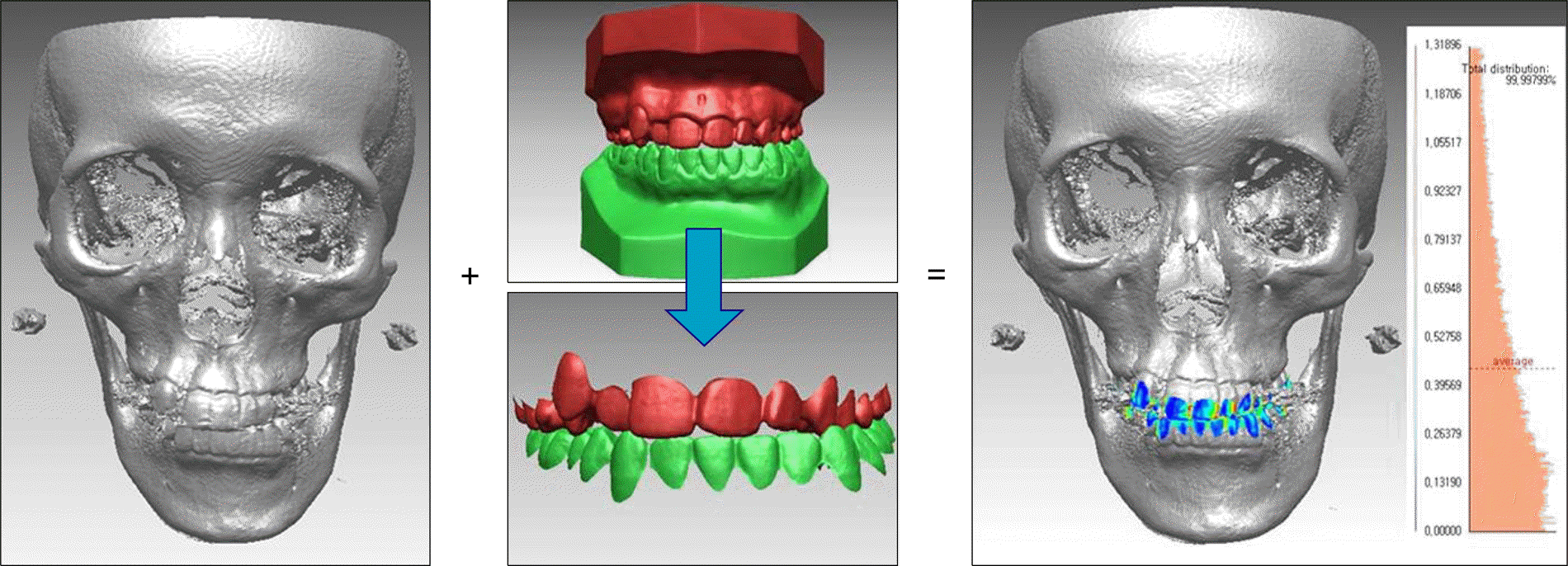
 | Fig 1.CBCT and scanned dental cast Images are integrated and displayed in colors on a millimeter scale. |
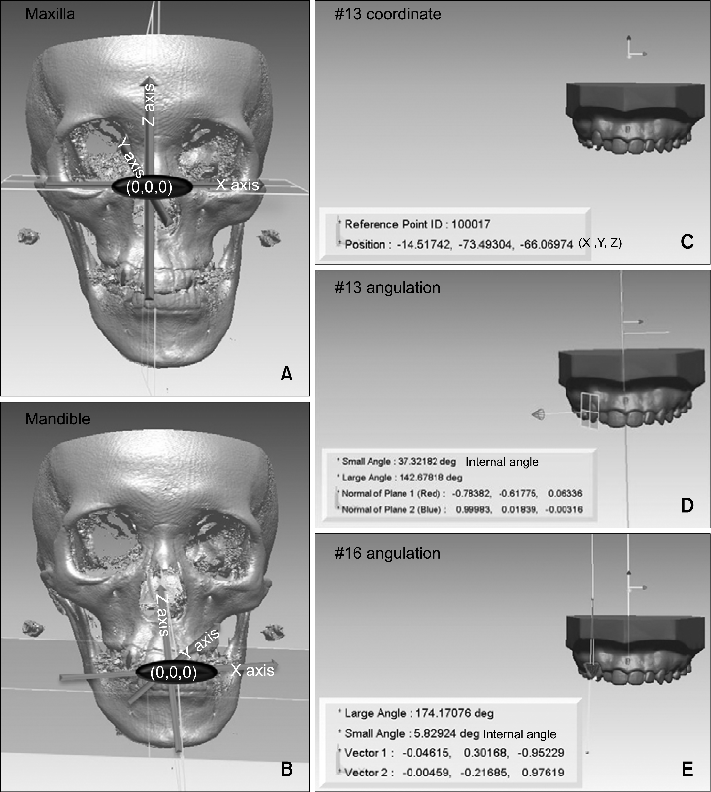
 | Fig 2.Reference coordinates and measurements. A, Maxilla, FH plane was constructed by connecting both sides of Po and right of Or. Sagittal plane is the line perpendicular to FH plane passing through Na and Ba. Coronal plane is the line perpendicular to FH plane and sagittal plane passing through right porion; B, mandible, Mn plane was constructed by connecting Me and both sides of Go. Sagittal plane is the line perpendicular to Mn plane passing through Pog and Me. Coronal plane is the line perpendicular to Mn plane and sagittal plane passing through right Go; C, tooth coordinates (X, transverse position; Y, antero-posterior position; Z, vertical position); D, canine angulation measured as the internal angle between tangential plane of FACC of canine and sagittal plane; E, molar angulation measured as the internal angle between a normal vector of the molar cusp tip occlusal plane and the Z-axis coordinate. |
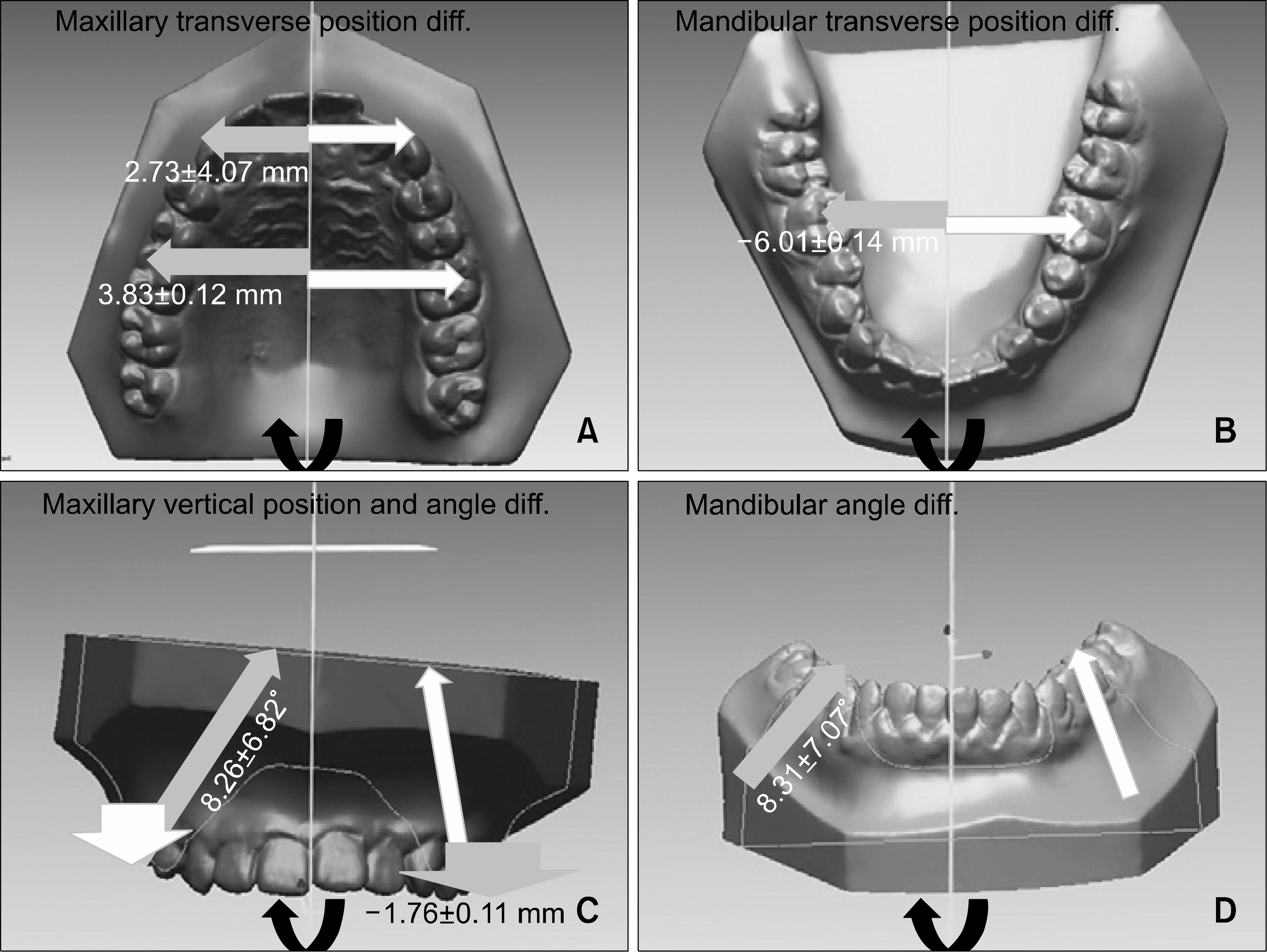
 | Fig 3.The tooth of maxillary and mandibular canine and first molars of facial asymmetry individuals were compensated, sotransverse, vertical position and angle showed deviated/non-deviated side differences. A, Deviated side of maxillary canines and first molars were positioned buccally than non-deviated side; B, deviated side of mandibular first molars were positioned lingually than non-deviated side; C, deviated side of maxillary first molars were angulated bucally, and non-deviated side of them were extruded than the other side; D, deviated side of mandibular first molars were angulated lingully than non-deviated side. |
Table 1.
Comparison of deviated/non-deviated side differences (dev.-ndev.) between control group and experimental group
Table 2.
Bivariate Pearson correlation between menton deviation and deviated/non-deviated side differences (dev.-ndev.)


 PDF
PDF ePub
ePub Citation
 Print
Print


 XML Download