Abstract
Objective:
The aim of this study was to evaluate the strain induced in the cortical bone surrounding an orthodontic microimplant during insertion.
Methods:
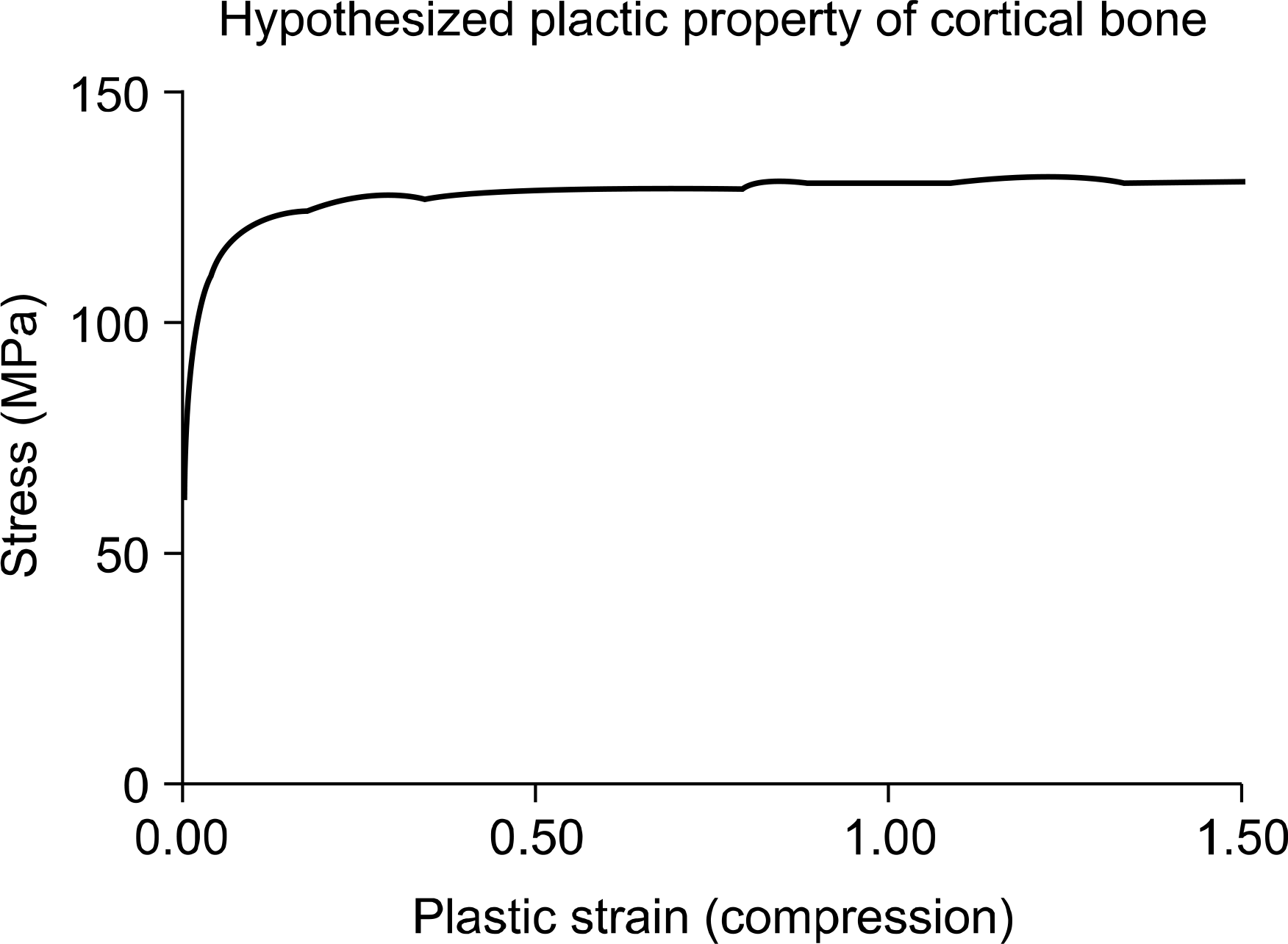
A 3D finite element method was used to model the insertion of a microimplant (AbsoAnchor SH1312-7, Dentos Co., Daegu, Korea) into 1 mm thick cortical bone with a pre-drilled hole of 0.9 mm in diameter. A total of 1,800 analysis steps was used to simulate the 10 turns and 5 mm advancement of the microimplant. A series of remesh in the cortical bone was allowed to accommodate the change in the geometry accompanied by the implant insertion.
Results:
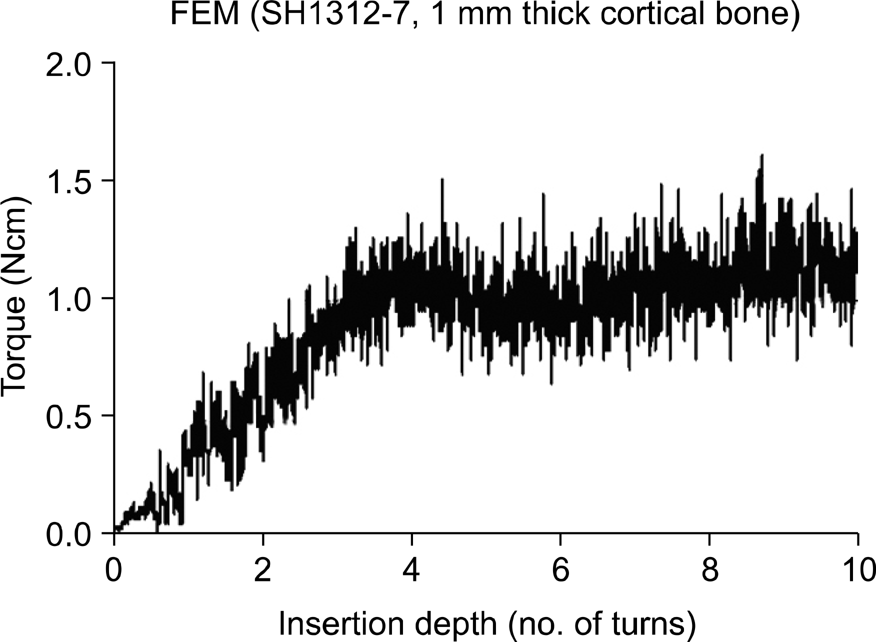
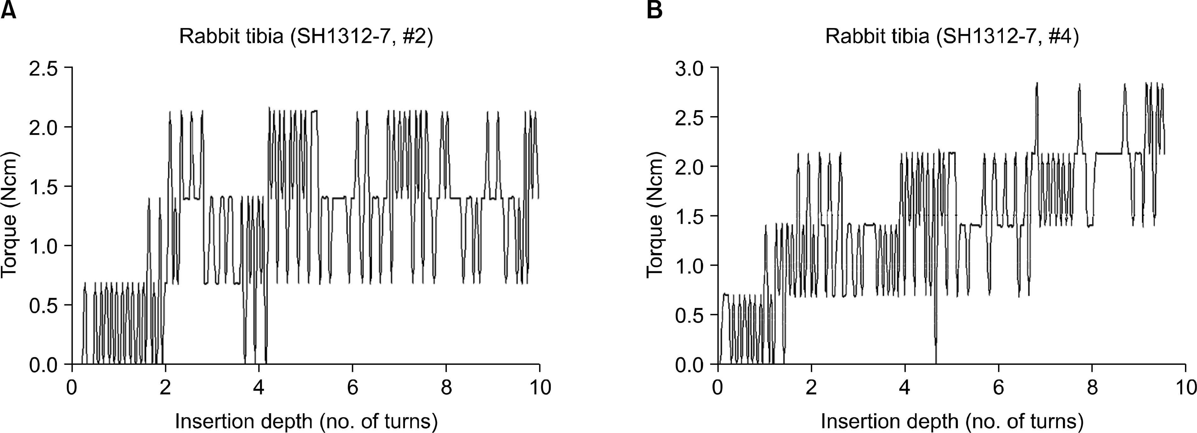
Bone strains of well higher than 4,000 microstrain, the reported upper limit for normal bone remodeling, was observed in the bone along the whole length of the microimplant. At the bone in the vicinity of the screw tip, strains of higher than 100% was recorded. The insertion torque was calculated at approximately 1.2 Ncm which was slightly lower than those measured from the animal experiment using rabbit tibias.
Go to : 
REFERENCES
1.Maniatopoulos C., Pilliar RM., Smith DC. Threaded versus porous-surfaced designs for implant stabilization in bone-endodontic implant model. J Biomed Mater Res. 1986. 20:1309–33.

2.Szmukler-Moncler S., Salama H., Reingewirtz Y., Dubruille JH. Timing of loading and effect of micromotion on bone-dental implant interface: review of experimental literature. J Biomed Mater Res. 1998. 43:192–203.

3.Pilliar RM., Lee JM., Maniatopoulos C. Observations on the effect of movement on bone ingrowth into porous-surfaced implants. Clin Orthop Relat Res. 1986. 208:108–13.

4.Frost HM. Wolff's law and bone's structural adaptation to mechanical usage: an overview for clinicians. Angle Orthod. 1994. 64:175–88.
5.Frost HM. Bone's mechanostat: a 2003 update. Anat Rec A Discov Mol Cell Evol Biol. 2003. 275:1081–101.

6.Rubin CT., Lanyon LE. Regulation of bone mass by mechanical strain magnitude. Calcif Tissue Int. 1985. 37:411–7.

7.Duyck J., Ronold HJ., Van Oosterwyck H., Naert I., Vander Sorten J., Ellingsen JE. The influence of static and dynamic loading on marginal bone reactions around osseointegrated implants: an animal experimental study. Clin Oral Implants Res. 2001. 12:207–18.

8.Motoyoshi M., Yano S., Tsuruoka T., Shimizu N. Biomechanical effect of abutment on stability of orthodontic mini-implant. A finite element analysis. Clin Oral Implants Res. 2005. 16:480–5.
9.Meyer U., Vollmer D., Runte C., Bourauel C., Joos U. Bone loading pattern around implants in average and atrophic edentulous maxillae: a finite-element analysis. J Maxillofac Surg. 2001. 29:100–5.

10.Meyer U., Joos U., Mythili J., Stamm T., Hohoff A., Fillies T, et al. Ultrastructural characterization of the implant/bone interface of immediately loaded dental implants. Biomaterials. 2004. 25:1959–67.

11.Tada S., Stegaroiu R., Kitamura E., Miyakawa O., Kusakari H. Influence of implant design and bone quality on stress/strain distribution in bone around implants: a 3-dimensional finite element analysis. Int J Oral Maxillofac Implants. 2003. 18:357–68.
12.Petrie CS., Williams JL. Comparative evaluation of implant designs: influence of diameter, length, and taper on strains in the alveolar crest. A three-dimensional finite-element analysis. Clin Oral Implants Res. 2005. 16:486–94.
13.Clelland NL., Gilat A. The effect of abutment angulation on stress transfer for an implant. J Prosthodont. 1992. 1:24–8.

14.Chun HJ., Shin HS., Han CH., Lee SH. Influence of implant abutment type on stress distribution in bone under various loading conditions using finite element analysis. Int J Oral Maxillofac Implants. 2006. 21:195–202.
15.Holmes DC., Loftus JT. Influence of bone quality on stress distribution for endosseous implants. J Oral Implantol. 1997. 23:104–11.
16.Kitagawa T., Tanimoto Y., Nemoto K., Aida M. Influence of cortical bone quality on stress distribution in bone around dental implant. Dent Mater J. 2005. 24:219–24.

17.Sevimay M., Turhan F., Kilicarslan MA., Eskitascioglu G. Three-dimensional finite element analysis of the effect of different bone quality on stress distribution in an implant-supported crown. J Prosthet Dent. 2005. 93:227–34.

18.Hansson S., Werke M. The implant thread as a retention element in cortical bone: the effect of thread size and thread profile: a finite element study. J Biomech. 2003. 36:1247–58.

19.Isidor F. Loss of osseointegration caused by occlusal load of oral implants. A clinical and radiographic study in monkeys. Clin Oral Implants Res. 1996. 7:143–52.

20.Dalstra M., Cattaneo PM., Melson B. Load transfer of minis-crews for orthodontic anchorage. Orthod. 2004. 1:53–62.
21.De Smet E., Jaecques SV., Jansen JJ., Walboomers F., Vander Sloten J., Naert IE. Effect of constant strain rate, composed of varying amplitude and frequency, of early loading on peri-implant bone (re)modelling. J Clin Periodontol. 2007. 34:618–24.

22.Sugiura T., Horiuchi K., Sugimura M., Tsutsumi S. Evaluation of threshold stress for bone resorption around screws based on in vivo strain measurement of miniplate. J Musculoskelet Neuronal Interact. 2000. 1:165–70.
23.Yu WJ., Kyung HM. A quantitative evaluation of cortical bone stresses influenced by diameter of orthodontic microimplant. J Korean Res Soc Dent Mater. 2007. 34:75–87.
Go to : 
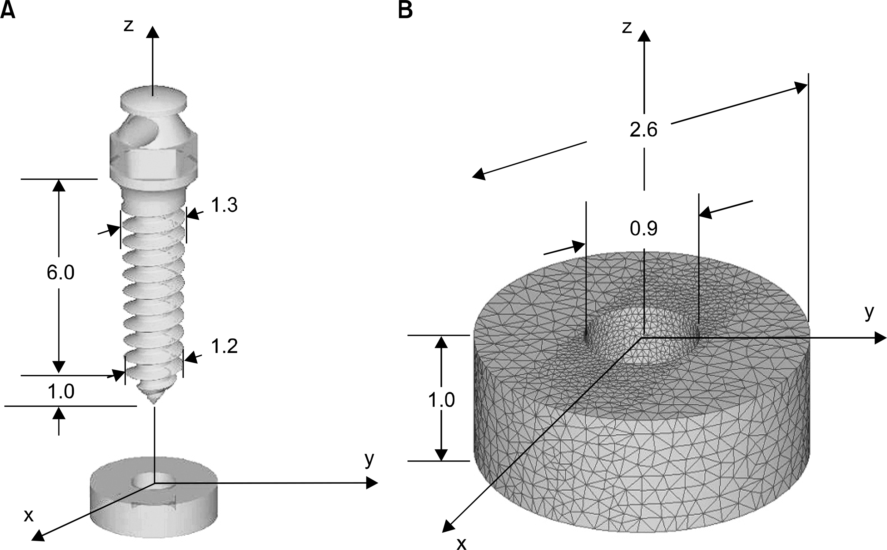 | Fig 1.Geometry of microimplant and cortical bone specimen together with axis system and important dimensions (implant: rigid, cortical bone: rigid-plastic, unit: mm). A, Geometry model; B, initial mesh of the cortical bone constructed of 30,706 tetrahedral element. |
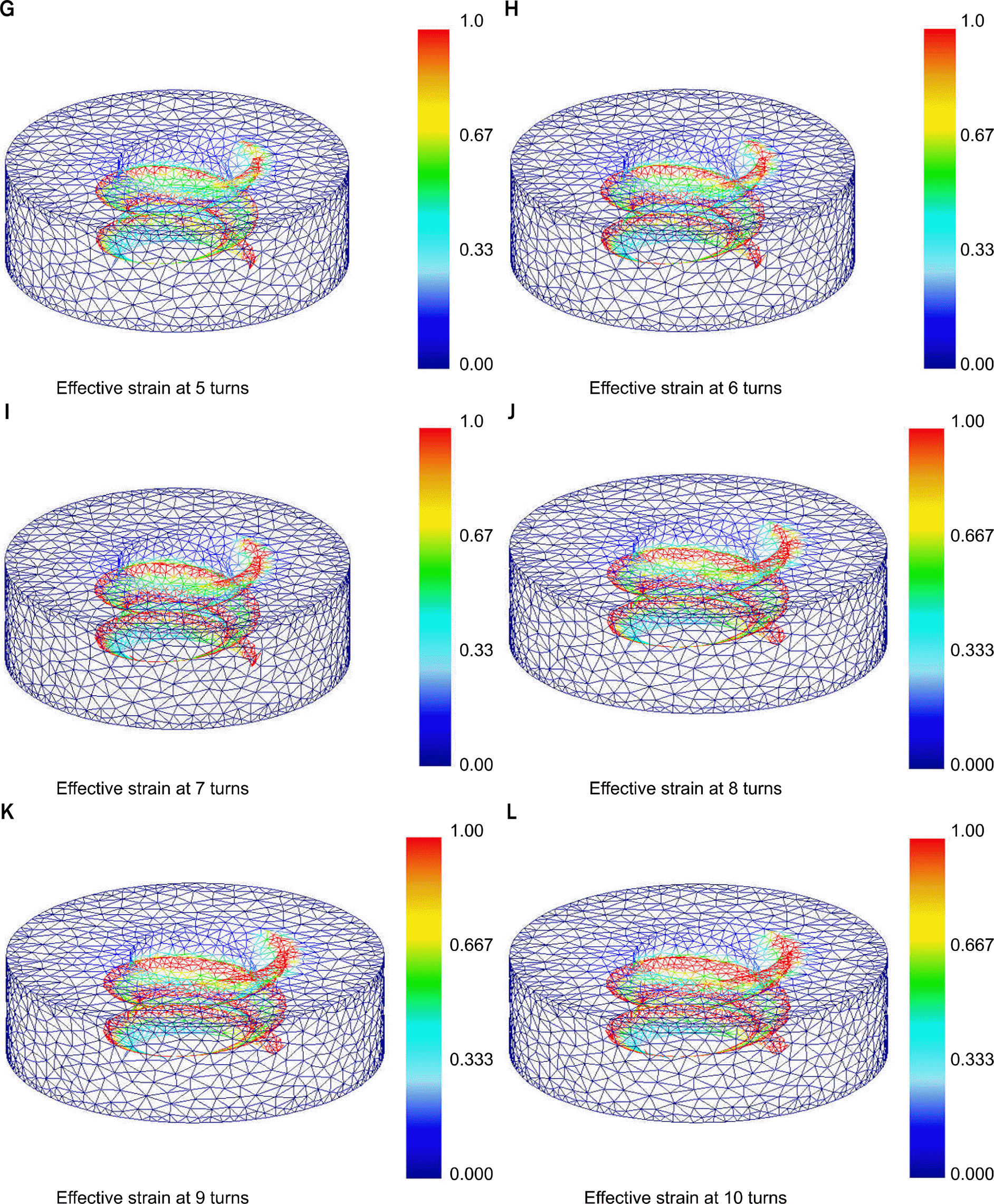 | Fig 3.A-L, Effective strain distribution in the cortical bone at 12 separate stages of microimplant insertion. |
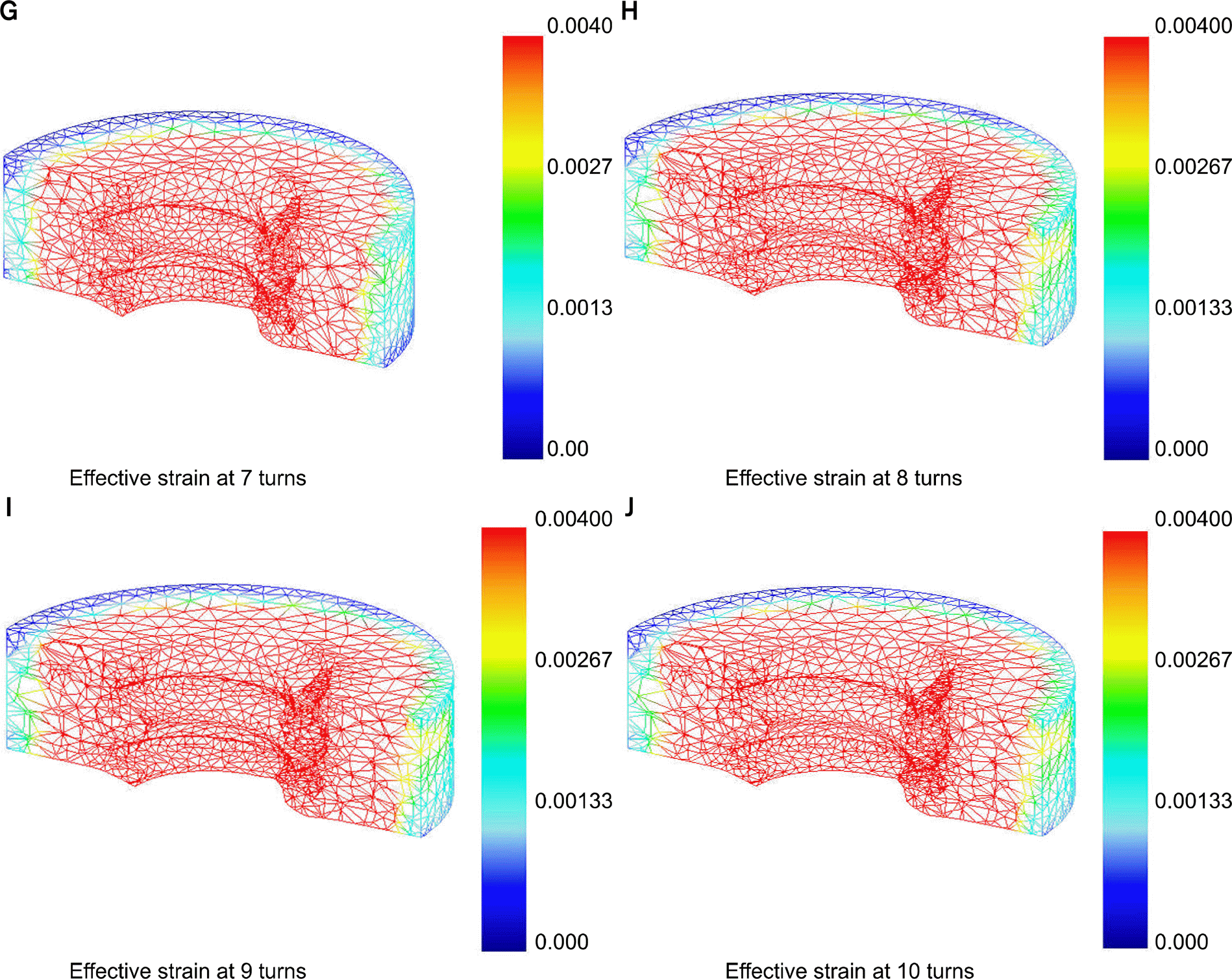 | Fig 4.
A-J, Strain distribution in the cortical bone at 9 separate stages of microimplant insertion with strains cut off at 4000μ-strain. |


 PDF
PDF ePub
ePub Citation
 Print
Print


 XML Download