

 PDF
PDF ePub
ePub Citation
 Print
Print


Figures and Tables
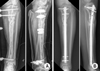
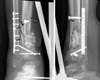
 | Fig. 2
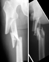
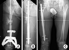
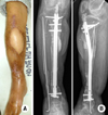
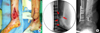
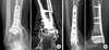
(A) Postoperative X-ray shows open reduction and internal fixation of all wedge fragments with multiple cerclage wiring and dynamic hip screw (DHS). This X-ray tells us how significant the amount of stripping of soft tissue attachment to the wedge fragments has been. (B) X-rays, taken after DHS removal and nailing due to delayed healing three months after initial open reduction with internal fixation.
|
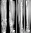
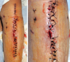
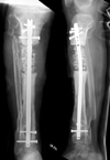
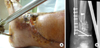
 | Fig. 3
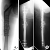
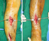
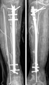
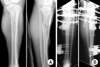
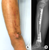
(A) Clinical photo shows that previous surgical scars along the lateral aspect of the thigh healed well. There were no clinical signs of infection, such as local heating sensation, redness, or sinus tract. (B) X-rays taken seven months after injury show loosening of the proximal interlocking screws and radiolucency around the nail, especially around the proximal part. Callus formation was not found and these findings were compatible with atrophic nonunion.
|
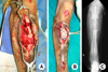
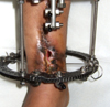
 | Fig. 4Clinical photo taken at the time of nail removal shows pus (arrow) draining from the medullary canal through the proximal interlocking screw hole upon removal of the loosened screw.
|
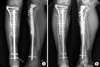
 | Fig. 5
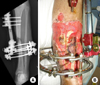
(A) X-ray taken after radical debridement with infected bone resection. (B) X-ray taken after second debridement and nailing, staged bone graft followed later. (C) Final follow-up X-ray taken 3.5 years after initial debridement shows fully consolidated grafted bone, with no recurrence of infection up until this point.
|
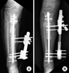
 | Fig. 6
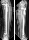
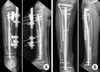
(A) Initial X-ray, tibia shaft fracture with severe comminution (open type G-A III). (B) X-ray taken after radical debridement and intramedullary nail insertion.
|
 | Fig. 7X-ray (antero-posterior and lateral view) taken at some point after nail removal and debridement of infected tissue. Note the segmental defect at the distal diaphysis and an Ilizarov frame was applied.
|
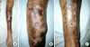
 | Fig. 8
(A) Clinical photos taken nine months after removal of the Ilizarov frame show complete healing of soft tissue and no signs of infection grossly. (B) X-rays show malalignment at both the proximal and distal 1/3rd of the shaft and nonunion at the distal fracture site.
|
 | Fig. 9Intraoperative clinical photos show no gross signs of infection on both proximal and distal lesions.
|
 | Fig. 10X-ray (antero-posterior and lateral view). Postoperative X-rays show realignment and fixation with intramedullary nailing.
|
 | Fig. 11
(A, B) Clinical photographs taken on postoperative day 6 show a small amount of pus discharge at the proximal tibial nonunion site. (C) Clinical photographs taken at the time of the first debridement show necrosis of the grafted bones and surrounding soft tissue.
|
 | Fig. 12
(A) Clinical photographs taken during the second debridement show the soft tissue and bone defect. Temporary Ex-Fix was performed and staged intramedullary nailing was planned. (B) Clinical photographs taken on the day when the Ex-Fix was removed and nailing was performed. Bone defect was filled with an antibiotic loaded polymethyl methacrylate cement spacer and the soft tissue defect was covered with an anterolateral thigh free flap. (C) Clinical photographs taken three days after nailing; the flap shows good soft tissue coverage.
|
 | Fig. 13
(A) A photograph taken three months after renailing; cementation show no gross sign of infection. (B) Radiographs show good alignment with the nail.
|
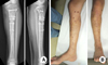
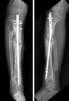
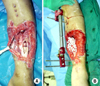
 | Fig. 14
(A) Initial tibia antero-posterior and lateral view show a high energy proximal tibia fracture (AO 42 B). (B) Postoperative X-rays show open reduction and wiring of the large wedge and hybride Ex-Fix as a definitive fixation. Significant stripping of the soft tissue around the wedge is expected during the procedure.
|
 | Fig. 15
(A) X-rays taken after removal of Ex-Fix three months after the index operation. Note a clearly visible fracture gap and almost no callus bridging across the nonunion site. (B) Clinical photographs show no signs of infection (redness, local heating sensation, and sinus tract).
|
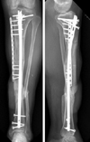
 | Fig. 16Postoperative X-rays (antero-posterior and lateral view) taken after intramedullary nailing and autologous bone graft.
|
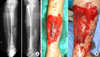
 | Fig. 17Clinical photographs taken on day 13 after nailing; bone graft shows delayed wound healing and serous discharge.
|
 | Fig. 18
(A) X-ray taken after radical debridement and intramedullary reaming and temporary fixation with Ex-Fix. Staged renailing was planned. (B) Latest follow-up X-rays taken three months after renailing. Note the polymethyl methacrylate space at the bone defect for which filling with staged bone graft is planned.
|
 | Fig. 19Clinical photos taken three years and six months after initial injury. (A) Soft tissue coverage was done properly with a free latissimus dorsi flap. (B) Note the two points of small sinus tracts centered over the previous surgical scar. (C) Note the additional sinus tract on the anteromedia aspect of the distal leg.
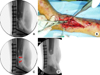
|
 | Fig. 20Tibia antero-posterior (AP) and lateral views taken three years and six months after injury. A round area of radiolucency centered on the proximal nonunion site is visible. Note the loosening of proximal interlocking screws. A round area of radiolucency centered on one of the distal locking screw holes also visible on AP view. The nail shifted anteromedially due to instability and spread of infection all along the medullary canal. Note the resorption around the nail.
|
 | Fig. 21
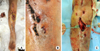
(A) Intra-operative photograph shows necrotic bone surrounded with infected granulation tissue. (B) Clinical photograph taken during the debridement. Intramedullary reaming was performed for debridement of the entire medullary canal. (C) X-ray taken after radical debridement and segmental bone resection. The medullary canal was filled with antibiotics impregnated polymethyl methacrylate coated flexible nail and the defect was additionally filled with a chain of PMMA beads.
|
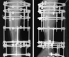
 | Fig. 23
(A) X-ray taken after osteotomy for bone transport over the intramedullary nail. (B) X-ray taken on completion of bone transport.
|
 | Fig. 24
(A) X-rays taken after bone graft at the docking site. The docking site was bridged with a lateral plate, which was placed using the minimally invasive plate osteosynthesis technique. With this plating, expected duration of Ex-Fix was reduced by 60%-70% compared to classical bone transport using external fixation only. (B) X-rays taken three years and six months after radical debridement and staged reconstruction with bone transport over the nail show complete healing and no recurrence of infection. The patient ended up 2 cm short compared to the contralateral side due to initial shortening.
|
 | Fig. 25
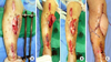
(A) Photograph shows initial soft tissue condition on the medial side of the distal tibia. (B) X-rays taken after the initial operation show staple marks along the medial side and multiple lag screws to the probably devitalized wedge fragments. The quality of initial debridement appeared to be not radical or thorough enough. Additional Ex-Fix was performed. (C) Clinical photograph taken two weeks after the initial operation shows severe infection with purulent discharge and skin necrosis along the incision. Note the attempt of primary closure under significant tension.
|
 | Fig. 26
(A) Clinical photograph taken one month after debridement and insertion of antibiotic impregnated polymethyl methacrylate cement beads and flap coverage. Note the breakdown of the flap margin due to discharge of pus from within. (B) X-ray taken at the time of referral. Note the devitalized wedge fragments still visible within the medullary canal.
|
 | Fig. 27X-rays (antero-posterior and lateral view) taken before the radical debridement. Removal of all devitalized wedge fragments (arrows) was planned from the beginning.
|
 | Fig. 28
(A-D) Intraoperative image before starting the debridement. Multiple devitalized wedge fragments were visible. (B) Removal of multiple devitalized wedge fragments from the medullary canal. They should have been removed at the time of the first operation and procedures followed afterwards. (C) Intraoperative C-arm image revealed sequestrums (arrow) that were not visible during the debridement as they were embedded within scar tissue. (D) Intraoperative C-arm image confirms the removal of all devitalized wedge fragments as it was planned.
|
 | Fig. 29
(A) Intraoperative photographs taken upon completion of debridement show the coin sized soft tissue defect. Acute shortening with the fibular ostectomy was performed for closure of the wound. (B) X-rays taken before and after shortening (arrows).
|
 | Fig. 30
(A) X-rays taken at the time of docking after bone transport over nail for reconstruction of bone defect. (B) X-rays show complete healing through staged reconstruction.
|
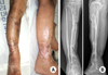
 | Fig. 31
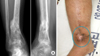
(A) X-rays taken one year and six months after trauma. Note the varus malunion at the distal metadiaphyseal junction and sclerosis around the previous fracture site. (B) Clinical photograph shows precarious soft tissue coverage with granulation and epithelization.
|
 | Fig. 32
(A) Intraoperative photographs show the incision through the previous surgical scar and resected necrotic bone segment. (B) Postoperative X-ray shows defect filled with a chain of polymethyl methacrylate beads. (C) X-ray taken after bone transport using the classic Ilizarov method.
|
 | Fig. 33Clinical photograph shows soft tissue condition at the time of docking, wound break down and recurrence of pus discharge. This wound was managed again with daily dressing change and epithelization over several weeks.
|
 | Fig. 34
(A) Clinical photo shows the wound managed with granulation and epithelization for several weeks again. (B) Postoperative X-rays show posterior plating and bone graft to avoid a medial incision through precarious soft tissue.
|
 | Fig. 35
(A) X-rays taken two years after posterior plating and bone graft. Additional bone graft was performed at another hospital before this failure. (B) X-ray, taken two years after the second posterior plating and third autogenous bone graft. Complete union was achieved with ankle fusion.
|
 | Fig. 36
(A) X-ray taken six weeks after initial management. Also, (B) clinical photography, the dessicated bone note the exposure of the dessicated bone segment due to an uncovered huge soft tissue defect.
|
 | Fig. 37
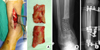
(A) Clinical photograph shows bone and soft tissue defect after radical debridement. (B) Defect filled with antibiotic impregnated polymethyl methacrylate cement beads and external fixator application.
|
 | Fig. 38
(A) Postoperative X-rays after debridement and intramedullary nail insertion. (B) Clinical photos before and after free flap for the huge pretibial soft tissue defect.
|

References
1. Motsitsi NS. Management of infected nonunion of long bones: the last decade (1996-2006). Injury. 2008; 39:155–160.

2. Oh JK, Hwang JH, Sahu D, Jun SH. Complication rate and pitfalls of temporary bridging external fixator in periarticular communited fractures. Clin Orthop Surg. 2011; 3:62–68.
3. Stucken C, Olszewski DC, Creevy WR, Murakami AM, Tornetta P. Preoperative diagnosis of infection in patients with nonunions. J Bone Joint Surg Am. 2013; 95:1409–1412.
 XML Download