Abstract
Objectives
The purpose of this study was to develop an approach to reduce the metal artifact that appears around pedicle screws, and thus to facilitate the evaluation of pedicle screw positions on CT scan images.
Summary of Literature Review
Metal artifact caused by pedicle screws significantly reduces the interpretability of computed tomography images.
Materials and Methods
We describe the development of an algorithm that processes CT scan images on a personal computer using a digital image enhancement technique. The algorithm improves CT images by transforming image pixel values using a proper transformation curve that takes into account the characteristic distribution pattern of metal artifact caused by pedicle screws made of titanium alloys. We implemented this algorithm in a program that reconstructs the resulting images in arbitrary planes and in axial, coronal, and sagittal planes. The software was tested with spiral CT scan images of 38 patients containing 190 pedicle screws.
Results
In all test cases, our algorithm generated images with less metal artifact, better soft tissue visualization and clearer screw outlines than conventional bone setting. In addition, images reconstructed in arbitrary planes increase the convenience and confidence of localizing screw positions.
REFERENCES
1). Crane R. A simplified approach to image processing: classical and modern techniques in C. New Jersey, Pren -tice Hall PTR: 110-143. 1997.
2). Kalender WA, Hebel R and Ebersberger J. Reduction of CT artifacts caused by metallic implants. Radiol. 164:576–577. 1987.

3). Pratt WK. Digital Image Processing. 2nd ed.New York: Wiley-Interscience;p. 263–322. 1991.
4). Robertson DD, Weiss PJ, Fishman EK, Magid D and Walker PS. Evaluation of CT techniques for reducing artifacts in the presence of metallic orthopedic implants. J Comput Assist Tomogr. 12:236–241. 1988.

5). Robertson DD, Yuan J, Wang G and Vannier MW. Total hip prosthesis metal artifact suppression using iterative deblurring reconstruction. J Comput Assist Tomogr. 21:293–298. 1997.
6). Wang G, Frei T and Vannier MW. Fast iterative algorithm for metal artifact reduction in X-ray CT. Acad Radiol. 7:607–614. 2000.

7). Yeom JS, Choy WS, Kim WJ, Kim HY, Kang JW, Kim YH, Kim NK and Lee JB. A patient-specific surgical simulation system for spinal screw insertion composed of virtual roentgenogram, virual C-arm, and rapid prototyping. J of Korean Orthop Assoc. 36:161–166. 2001.
Fig. 1.
Postoperative CT scan images in soft tissue setting (A) and bone setting (B) show metal artifact appearing around the pedicle screws.
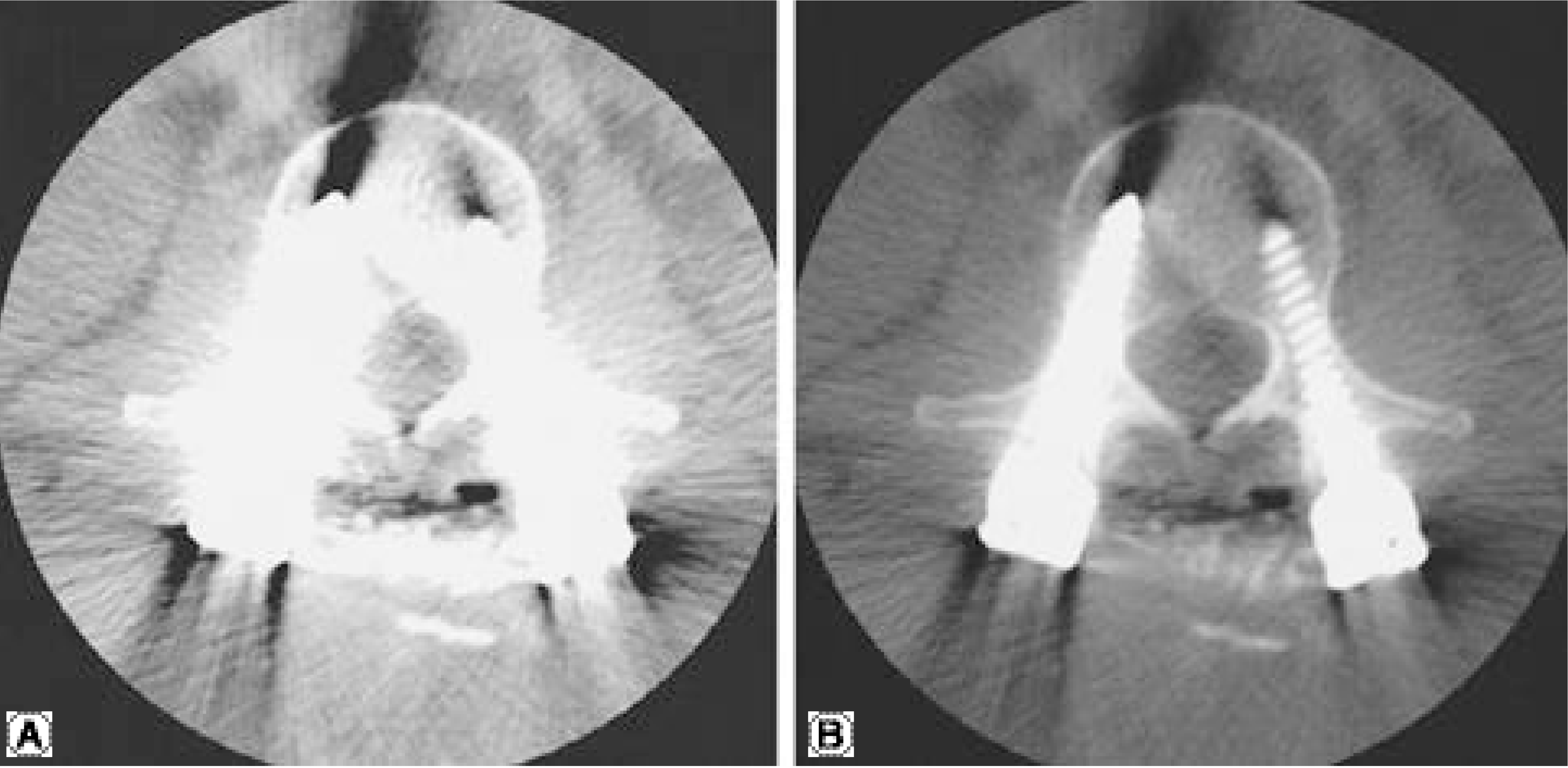
Fig. 2.
Two reconstructed three-dimensional images of a screw system demonstrate difference in thickness of screws according to difference in threshold values (A.2000, B. 2500).
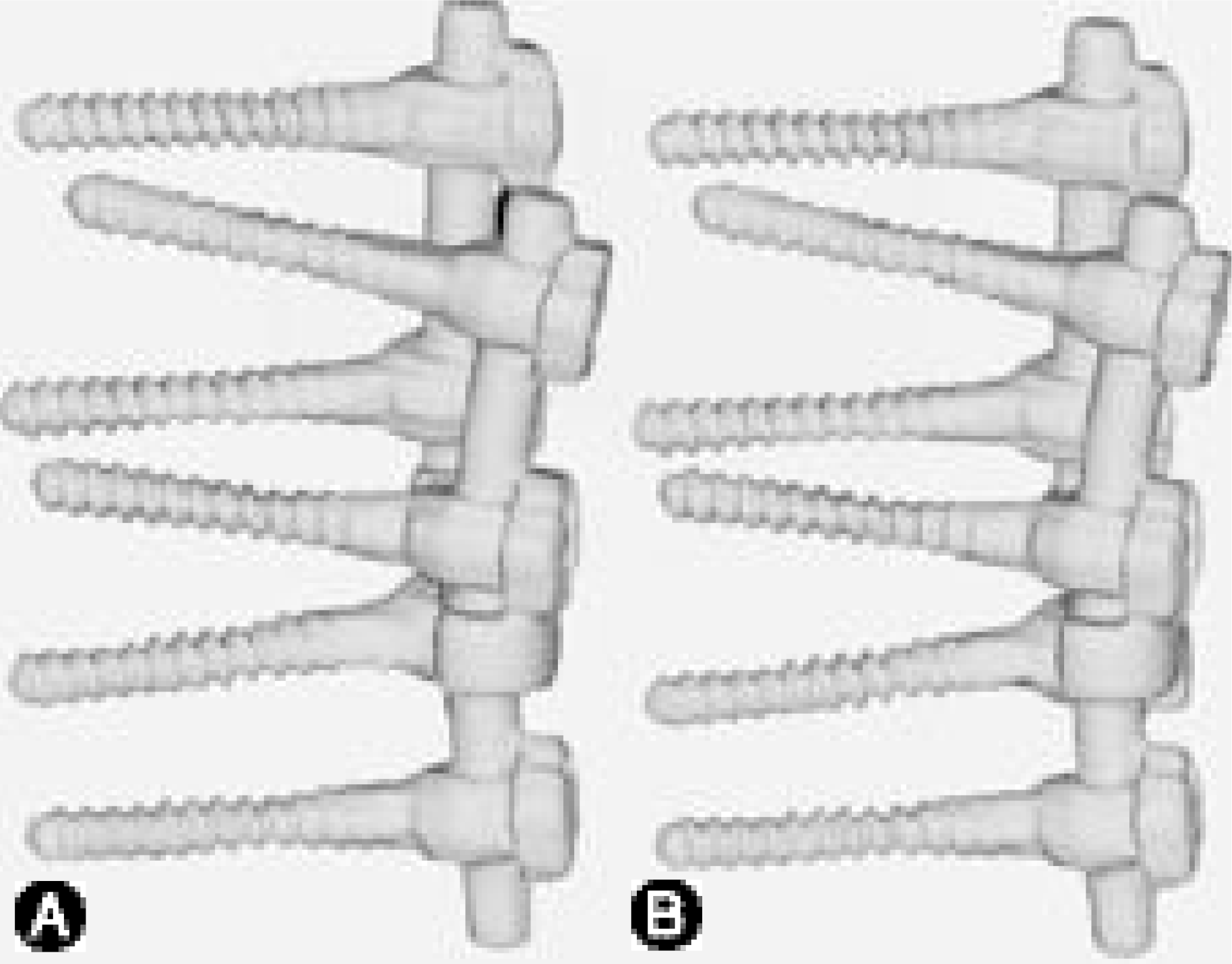
Fig. 3.
Two methods for analysis of Hounsfield numbers of CT scan images are shown. A. Pixel values are presented by a line profile. B. Pixel values are tabulated.
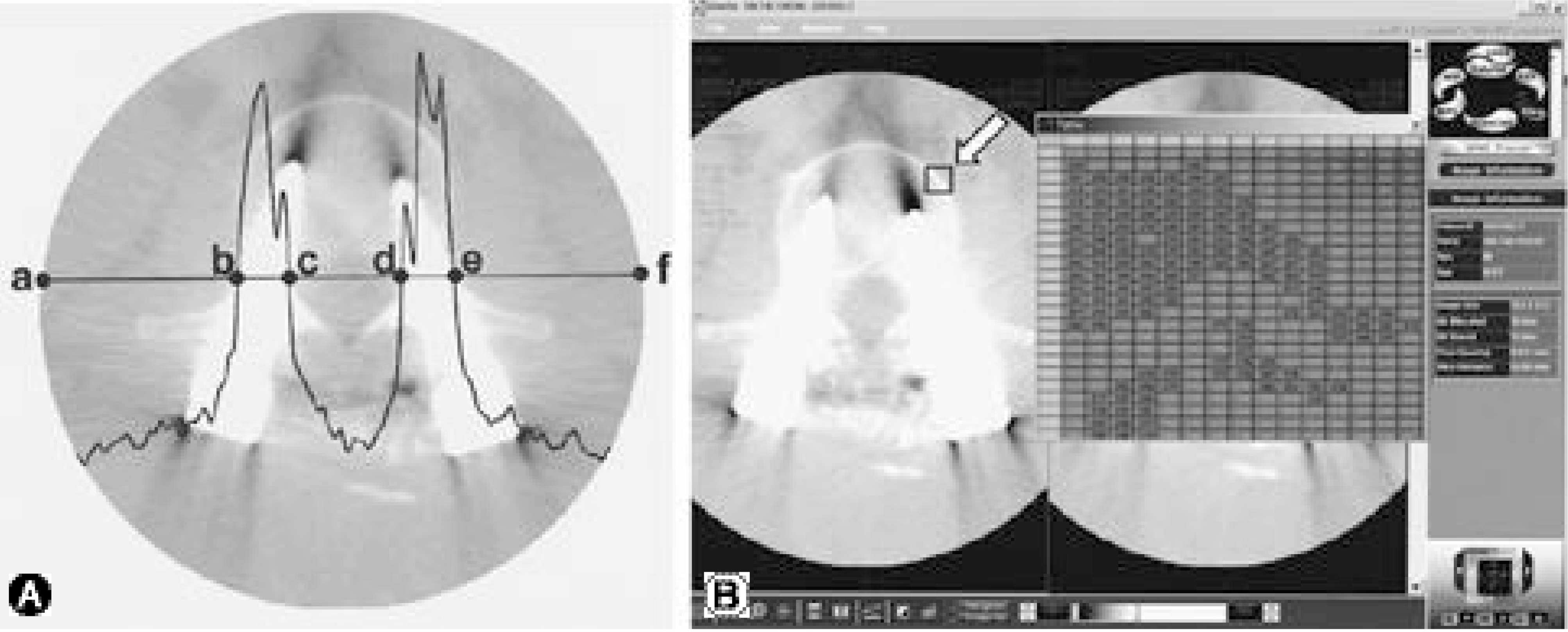
Fig. 4.
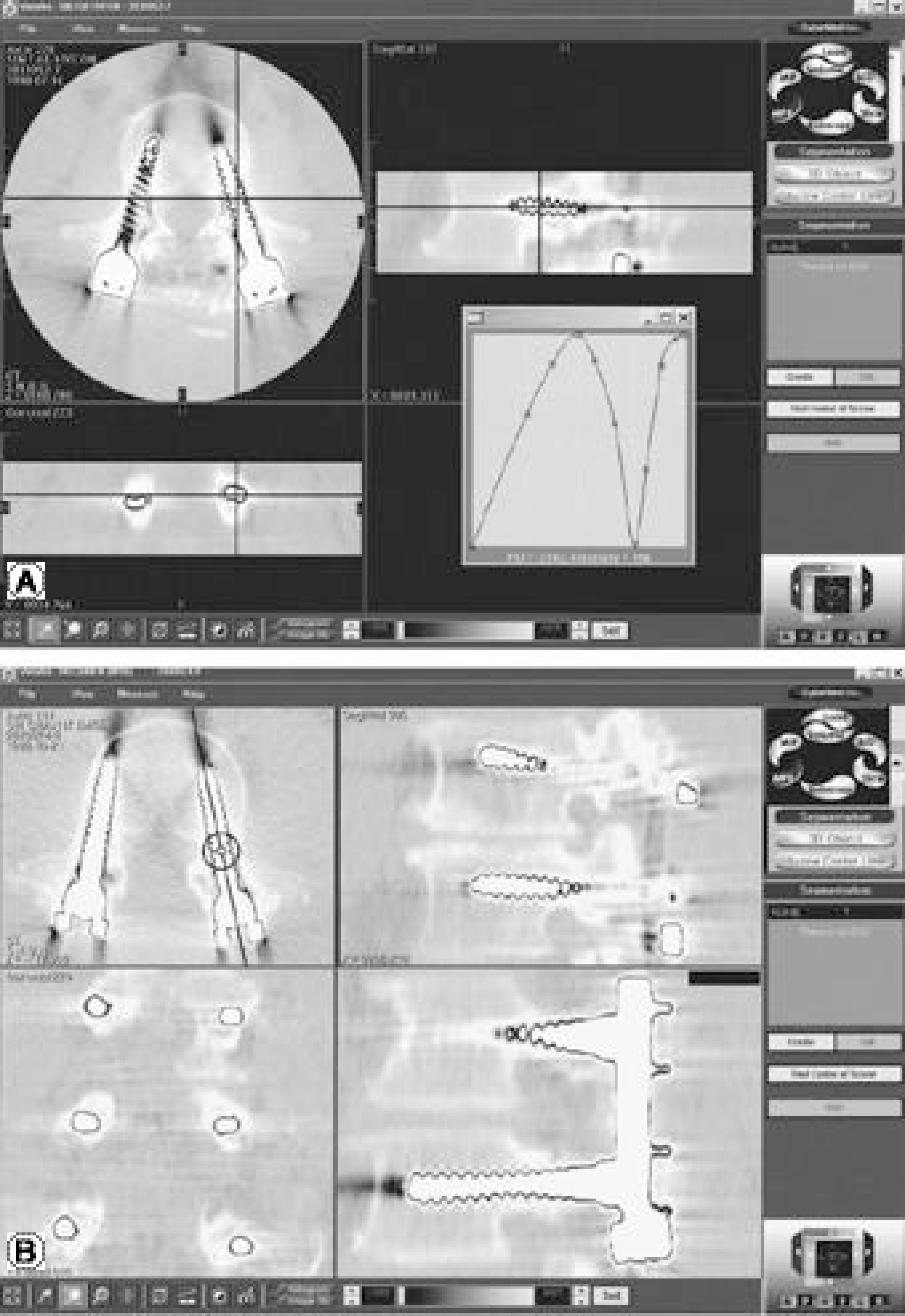
Pixel value remapping using the first curve is shown. The pixel values are converted to some other values according to the curve (A). On the resulting image, metal artifact is reduced, and the screw outlines are displayed (B). It also provides better visualization of soft tissue than the bone setting.
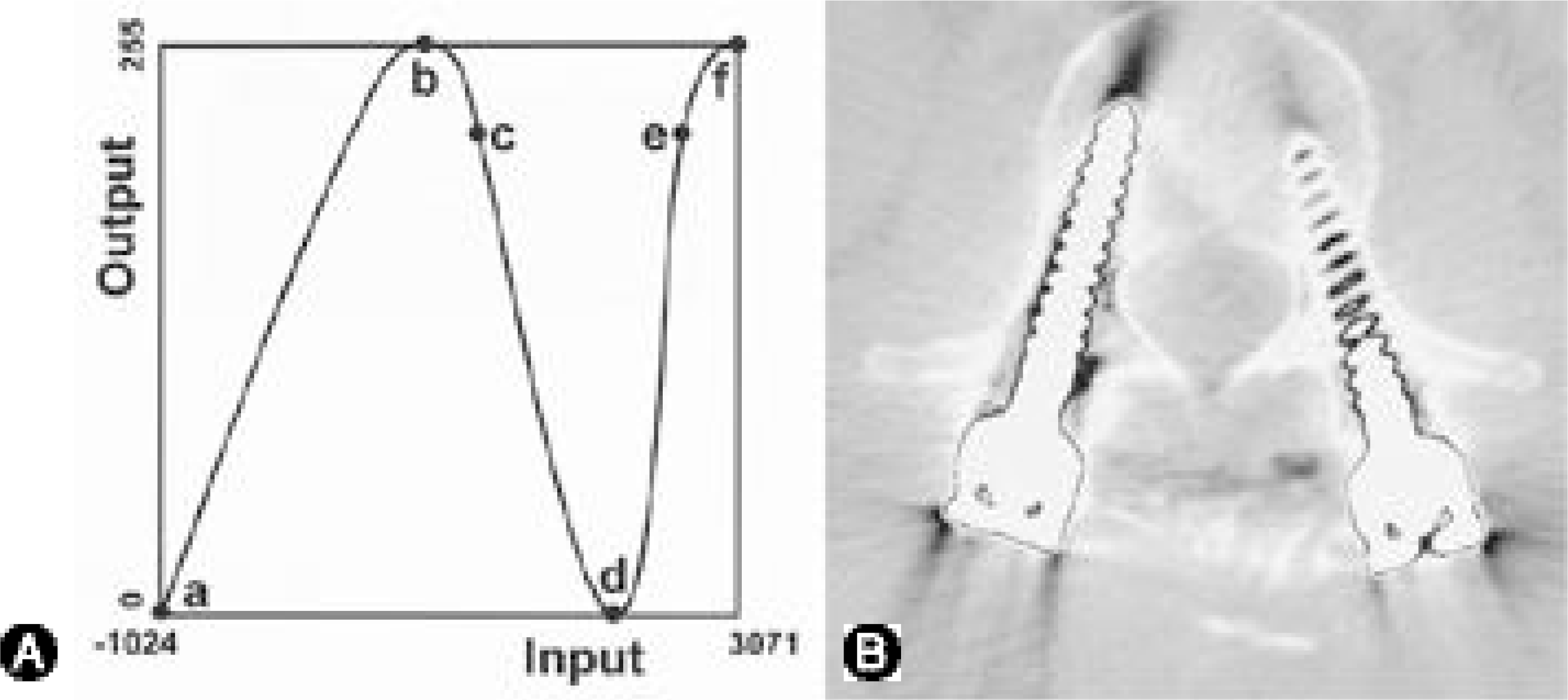
Fig. 5.
Pixel value remapping using the second curve (A) results in an image with clear outlines of both the screws and bony structures (B), which is more useful in determining screw position than the image produced by the first curve (C).

Fig. 6.
User interface of the final program is shown. A. Images in axial, coronal, and sagittal windows are displayed simultaneously, and ‘ line indicators’ on each window interre-late the image contents. B. Once the arbitrary plane reconstruction function is turned on, and a user places a line on any of the three multi-planar reconstruction images, then an image perpendicular to the plane and including the line is displayed on the right lower window.


 PDF
PDF ePub
ePub Citation
 Print
Print


 XML Download