

 PDF
PDF ePub
ePub Citation
 Print
Print


Abstract
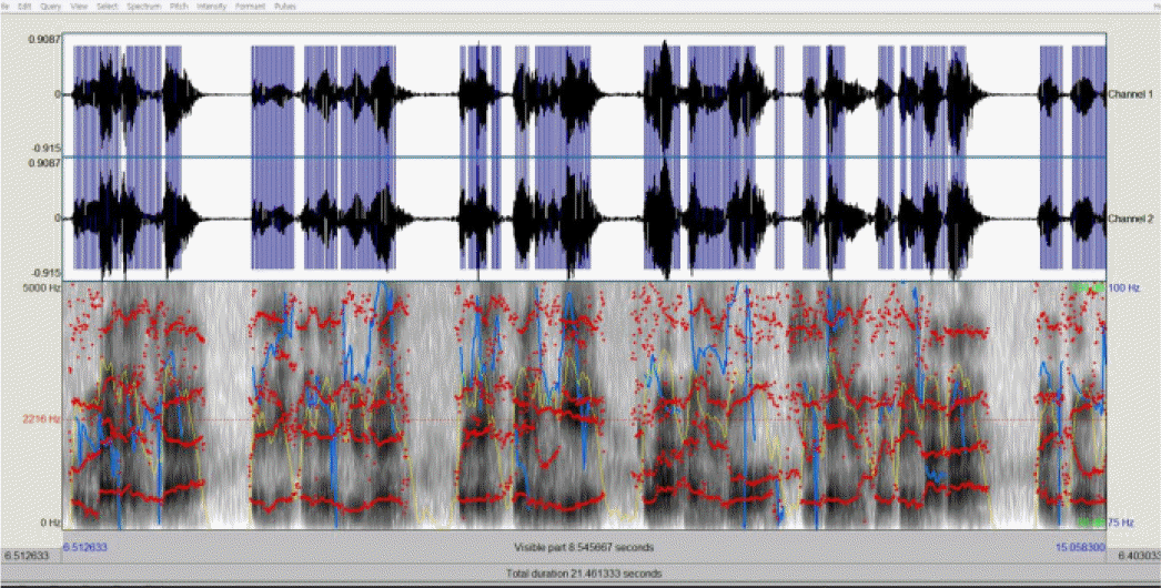
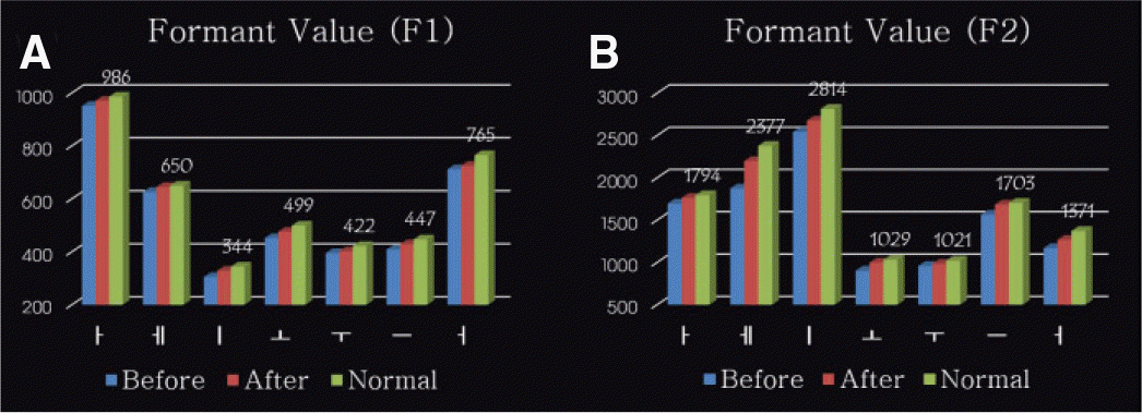
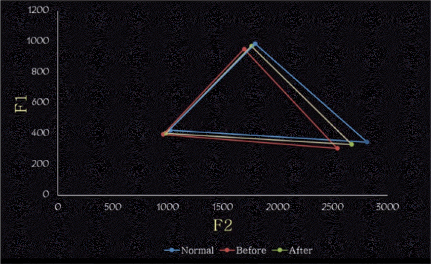
Recently, there are cases where anterior esthetic prostheses are fabricated for better esthetics, but biologic, mechanical factors could be overlooked, too focusing on esthetic factor. This leads to changes in neutral zone, dentition, position of tongue and lips, occlusion and anterior guidance causing inaccurate pronunciation. Therefore, consideration of systematic diagnosis and treatment procedure are required. In this case, prosthesis was refabricated through a systematic diagnosis and treatment procedure using four factor (acoustic analysis, esthetic analysis, occlusion, neutral zone) for the patient who complained of inaccurate pronunciation and esthetics of the fixed prosthesis fabricated 10 years ago. Thus, by promoting functional, esthetic recovery, this case report demonstrates satisfying results to both the patient and dentist. (J Korean Acad Prosthodont 2016;54:413-22)
Go to : 
REFERENCES
1.Palmer JM. Analysis of speech in prosthodontic practice. J Prosthet Dent. 1974. 31:605–14.

2.Kent RA., Read C. The acoustic analysis of speech. 2nd ed.Albany: NY; Thomson Learning;2002. p. 1–60.
3.Ladefoged P. A course in phonetics. 5th ed.Wadsworth: Cengage learning;2006. p. 211–36.
4.Zarb GA., Bolender CL., Eckert SE., Fenton AH., Jacob RF., Mericske-Stern R. Prosthodontic treatment for edentulous patients: complete dentures and implant-supported prostheses. 12th ed.St. Louis: Mosby;2003. p. 379–88.
5.Vaz Freitas S., Melo Pestana P., Almeida V., Ferreira A. Integrating voice evaluation: correlation between acoustic and audio-perceptual measures. J Voice. 2015. 29:390. .e1-7.
6.Ahn J., Kim G., Kim YH., Hong J. Acoustic analysis of vowel sounds before and after orthognathic surgery. J Craniomaxillofac Surg. 2015. 43:11–6.
7.Burris C., Vorperian HK., Fourakis M., Kent RD., Bolt DM. Quantitative and descriptive comparison of four acoustic analysis systems: vowel measurements. J Speech Lang Hear Res. 2014. 57:26–45.
8.Fradeani M. Evaluation of dentolabial parameters as part of a comprehensive esthetic analysis. Eur J Esthet Dent. 2006. 1:62–9.
9.Calamia JR., Levine JB., Lipp M., Cisneros G., Wolff MS. Smile design and treatment planning with the help of a comprehensive esthetic evaluation form. Dent Clin North Am. 2011. 55:187–209. vii.
10.Mistry S. Principles of smile design-demystified. J Cosmet Dent. 2012. 28:116–24.
11.Alpert RL. A method to record optimum anterior guidance for restorative dental treatment. J Prosthet Dent. 1996. 76:546–9.
12.Sabek M., Trévelo A. Alternative procedure for reconstructing anterior guidance using an autopolymerizing resin pattern. J Prosthet Dent. 1996. 76:550–3.
13.Thornton LJ. Anterior guidance: group function/canine guidance. A literature review. J Prosthet Dent. 1990. 64:479–82.
14.Gross MD., Cardash HS. Transferring anterior occlusal guidance to the articulator. J Prosthet Dent. 1989. 61:282–5.
15.Nemcovsky CE., Gross MD. Transferring provisional restorations to final master casts. J Oral Rehabil. 1994. 21:157–63.
16.Porwal A., Sasaki K. Current status of the neutral zone: a literature review. J Prosthet Dent. 2013. 109:129–34.
17.Al-Magaleh WR., Swelem AA., Shohdi SS., Mawsouf NM. Setting up of teeth in the neutral zone and its effect on speech. Saudi Dent J. 2012. 24:43–8.
18.Ikebe K., Okuno I., Nokubi T. Effect of adding impression material to mandibular denture space in Piezography. J Oral Rehabil. 2006. 33:409–15.
Go to :
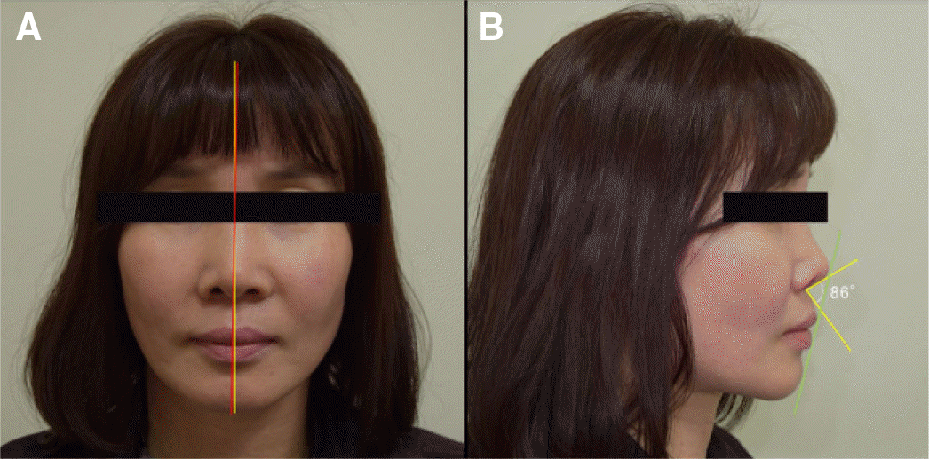 | Fig. 2.Initial extraoral examination. (A) Facial midline with the midline of central incisors in frontal view, (B) Rickett's E-plane indicating the distance to the upper lip less than 4 mm and nasio-labial angle less than 90° in lateral view. |
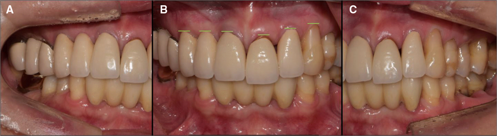 | Fig. 3.Initial intraoral examination. (A) Old prosthesis in right lateral view, (B) Generalized gingival recession and inappropriate zenith line in frontal view, (C) Extrusion of the maxillary left central incisor in left lateral view. |
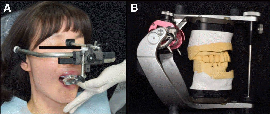 | Fig. 5.Semi-articulator mounting procedures for diagnosis. (A) Facebow transfer, (B) Mounting the diagnostic model to an articulator in lateral view. |
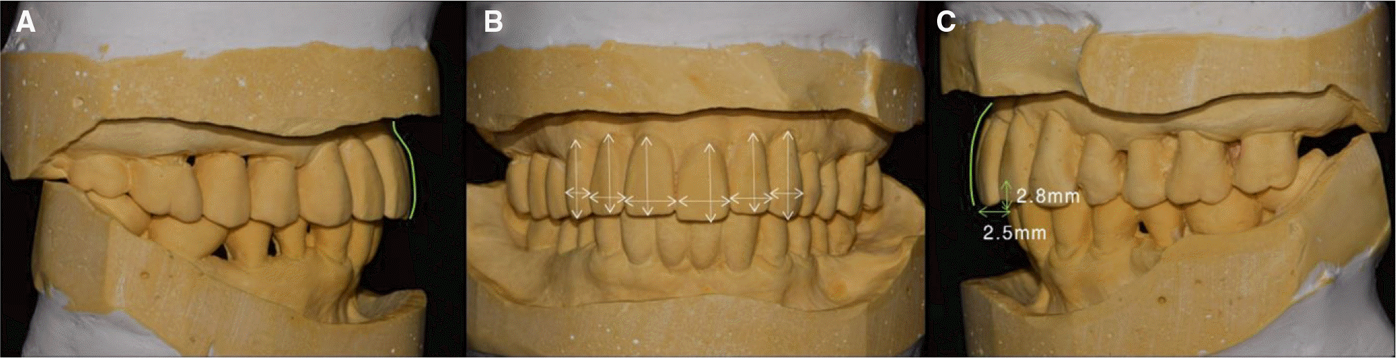 | Fig. 6.Analysis of diagnostic model. (A) Inappropriate emergence profile in right lateral view, (B) Lower width/length ratio of maxillary anterior teeth in frontal view, (C) Excessive overjet and overbite in left lateral view. |
 | Fig. 7.First temporary bridge fabrication by generalized anterior guidance. (A) Right lateral view, (B) Frontal view, (C) Left lateral view. |
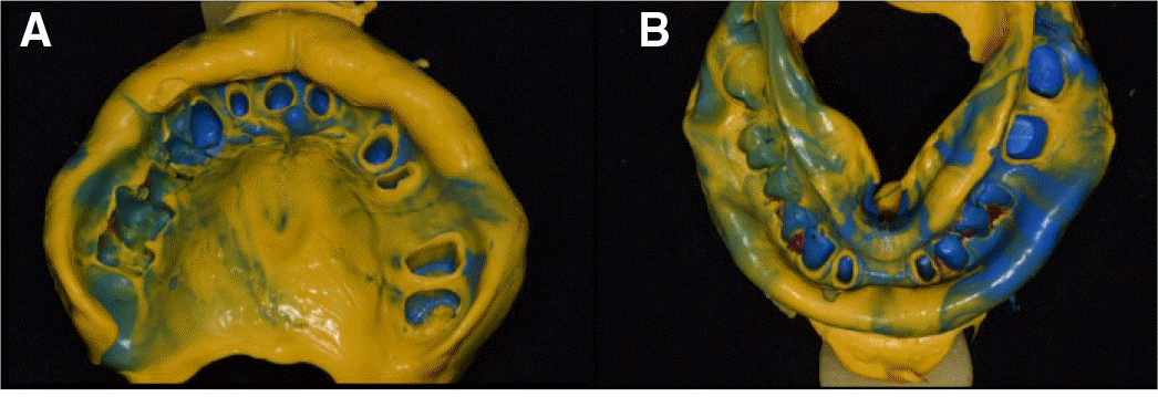
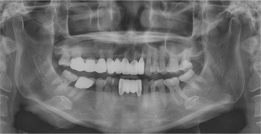
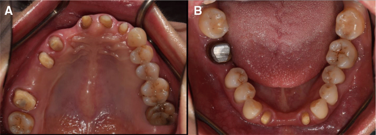 | Fig. 8.Abutment evaluation after old prosthesis removal. (A) Maxillary occlusal view, (B) Mandibular occlusal view. |
 | Fig. 9.Secondary temporary bridge fabrication by piezography technique and generalized anterior guidance. (A) Right lateral view, (B) Frontal view, (C) Left lateral view. |
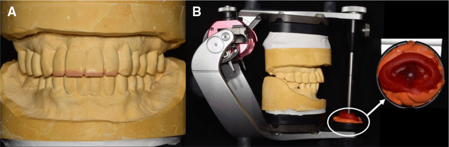 | Fig. 10.Customized anterior guidance table fabrication. (A) Increased length of maxillary central and lateral teeth in diagnostic model, (B) Customized anterior guidance table. |
 | Fig. 11.Full contour wax-up try-in for final temporary bridge fabrication. (A) Right lateral view, (B) Frontal view, (C) Left lateral view. |
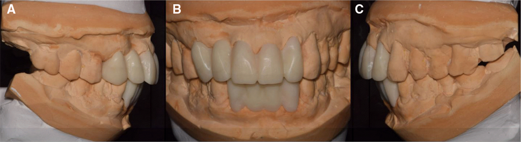
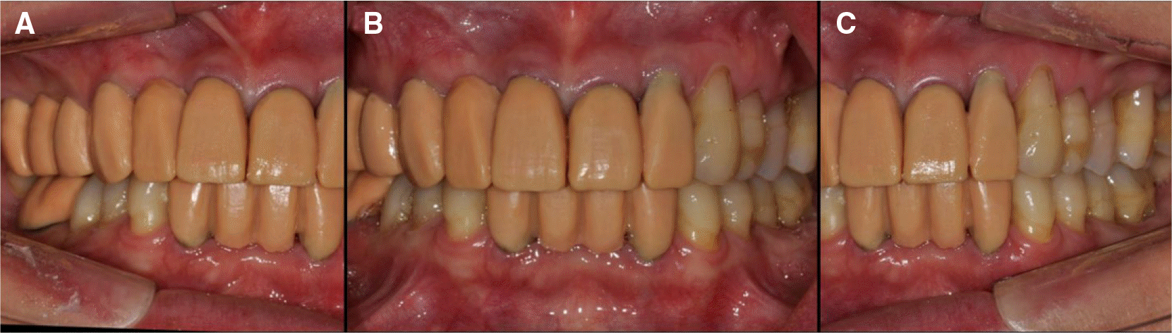
 | Fig. 12.Third and final temporary bridge fabrication by customized anterior guidance. (A) Right lateral view, (B) Frontal view, (C) Left lateral view. |
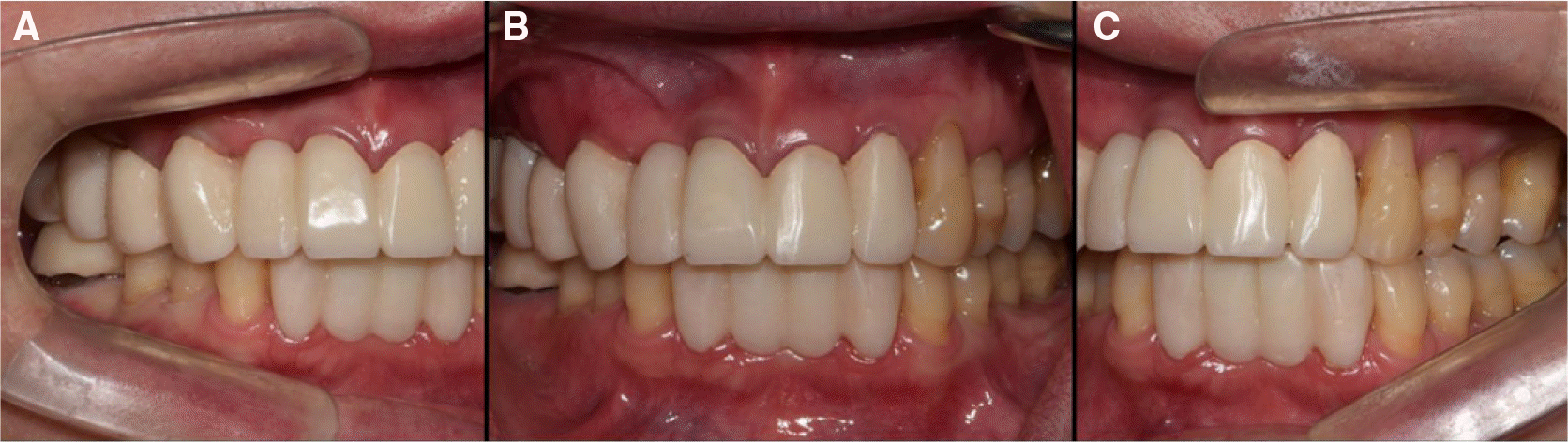
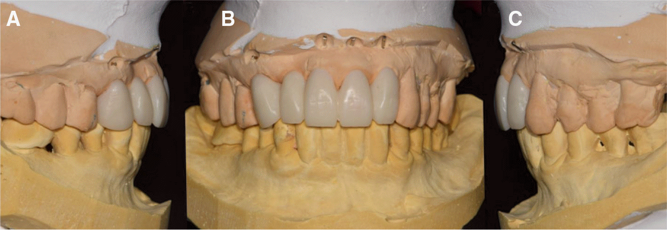 | Fig. 13.Fourth temporary bridge fabrication. (A) Right lateral view, (B) Frontal view, (C) Left lateral view. |
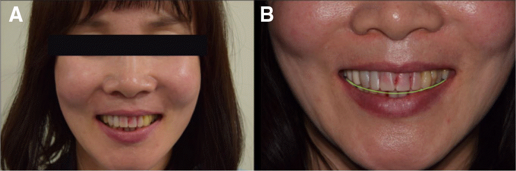
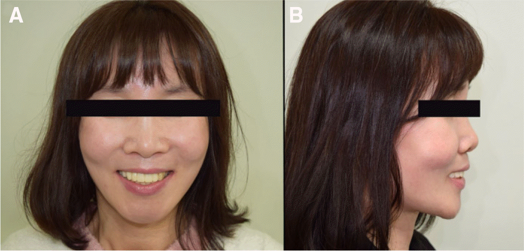 | Fig. 14.Final temporary bridge evaluation by smile line. (A) Improved smile line in frontal view, (B) Improved upper lip line in lateral view. |
 | Fig. 16.Duplicated final temporary bridge fabrication for CAD-CAM. (A) Maxillary temporary bridge, (B) Mandibular temporary bridge. |
 | Fig. 17.Duplicated final temporary bridge evaluation by smile line. (A) Frontal view, (B) Improved smile line. |
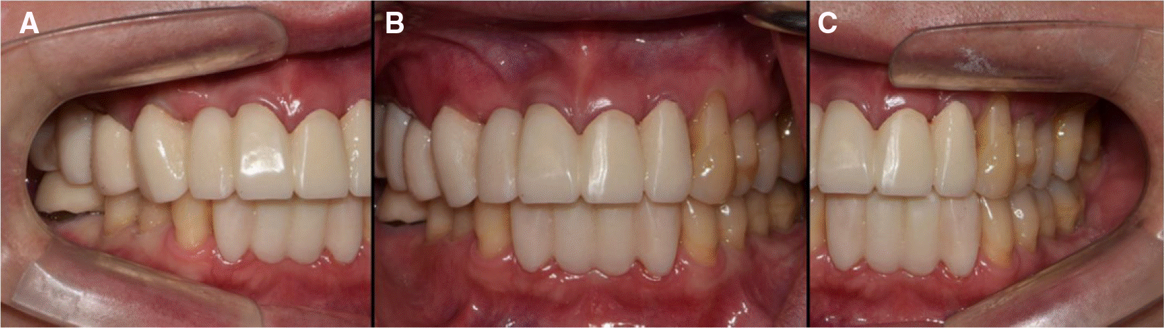
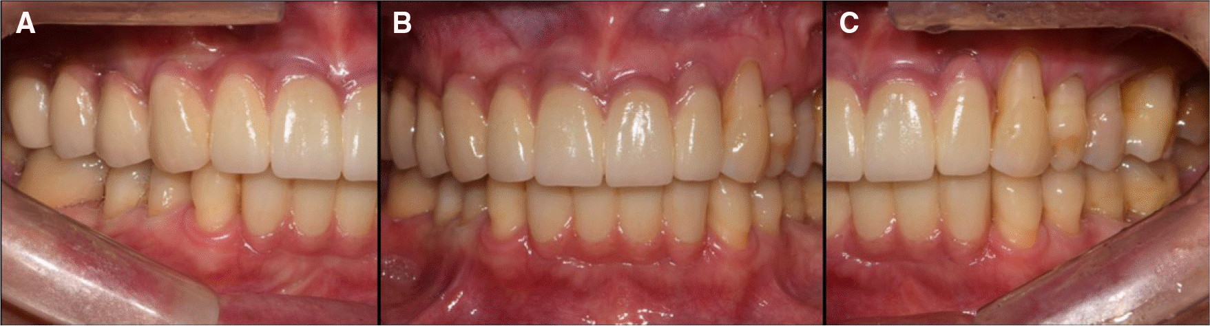 | Fig 18.Final prosthesis fabricaion by calculating the length of the teeth using the width/length ratio of 78%. (A) Right lateral view, (B) Determination of the size of the lateral incisors and canines using principles of tooth proportions, the "golden proportion" in frontal view, (C) Left lateral view. |
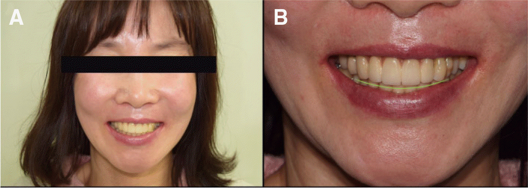 | Fig 19.Smile line evaluation of final prosthesis. (A) Frontal view, (B) Improved smile line. |
 XML Download