Abstract
With the recent progress of digital technology, the computer guided surgery utilizing a guide template in the placement of implant has been actively performed, and the method employing the intraoral scanner at the implant prosthesis introduced. Fabrication method of the guide template can be largely classified into design-related rapid prototyping (RP) system and vector milling system, and each of the method has its own weakness in the clinical application despite of excellent accuracy. Thus, in this case study, a working model was fabricated by the wax RP technology using images acquired by CBCT and an intraoral scanner, and the metal bushing was picked up with orthodontic resin cast upon the wax model. Using this method, a surgical guide template was fabricated and used in surgery. From this, we could obtain a satisfactory outcome clinically in the implant placement and the fabrication of the final prostheses and thus report this case herein.
Go to : 
REFERENCES
1. Fortin T, Champleboux G, Bianchi S, Buatois H, Coudert JL. Precision of transfer of preoperative planning for oral implants based on cone-beam CT-scan images through a robotic drilling machine. Clin Oral Implants Res. 2002; 13:651–6.

2. Scherer U, Stoetzer M, Ruecker M, Gellrich NC, von See C. Template-guided vs. non-guided drilling in site preparation of dental implants. Clin Oral Investig. 2014 Oct 30.

3. Park JM, Yi TK, Jung JK, Kim Y, Park EJ, Han CH, Koak JY, Kim SK, Heo SJ. Accuracy of 5-axis precision milling for guided surgical template. J Korean Acad Prosthodont. 2010; 48:294–300.

4. Park JM, Yi TK, Koak JY, Kim SK, Park EJ, Heo SJ. Comparison of five-axis milling and rapid prototyping for implant surgical templates. Int J Oral Maxillofac Implants. 2014; 29:374–83.

5. Fortin T, Champleboux G, Lormé e J, Coudert JL. Precise dental implant placement in bone using surgical guides in con-junction with medical imaging techniques. J Oral Implantol. 2000; 26:300–3.

6. Kim SY, Kim MJ, Han JS, Yeo IS, Lim YJ, Kwon HB. Accuracy of dies captured by an intraoral digital impression system using parallel confocal imaging. Int J Prosthodont. 2013; 26:161–3.

7. Ender A, Mehl A. In-vitro evaluation of the accuracy of conventional and digital methods of obtaining full-arch dental impressions. Quintessence Int. 2015; 46:9–17.
8. Talwar N, Chand P, Singh BP, Rao J, Pal US, Ram H. Evaluation of the efficacy of a prosthodontic stent in determining the position of dental implants. J Prosthodont. 2012; 21:42–7.

9. Valente F, Schiroli G, Sbrenna A. Accuracy of computer-aided oral implant surgery: a clinical and radiographic study. Int J Oral Maxillofac Implants. 2009; 24:234–42.
10. Youk SY, Lee JH, Park JM, Heo SJ, Roh HK, Park EJ, Shin IH. A survey of the satisfaction of patients who have undergone implant surgery with and without employing a computer-guided implant surgical template. J Adv Prosthodont. 2014; 6:395–405.

11. Wismeijer D, Mans R, van Genuchten M, Reijers HA. Patients' preferences when comparing analogue implant impressions using a polyether impression material versus digital impressions (Intraoral Scan) of dental implants. Clin Oral Implants Res. 2014; 25:1113–8.

Go to : 
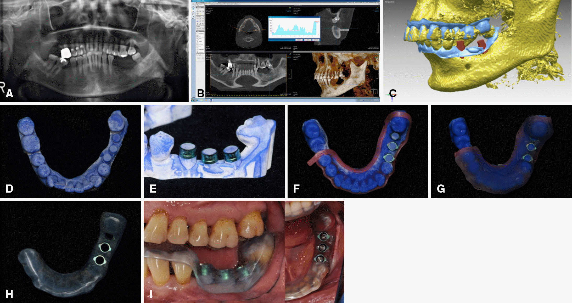
 | Fig. 1.Surgical template fabrication and implant placement. (A) Initial panoramic X-ray. (B) Analysis by CBCT. (C) CBCT image (DCM format) and intraoral scan data (STL format) were superimposed by a best fit algorithm. (C) Planned implant location information and normal anatomic structure were printed into wax model by rapid prototyping machine. (D) Fabricated wax-based RP model. (E) Guide bushings were placed onto the planned position. (F) Block out was made before the application of framework material. (G) Resin pouring. (H) Completed surgical template. (I) Template was tried in the patient's mouth. Drilling and implant placement was performed through the metal bushings. |
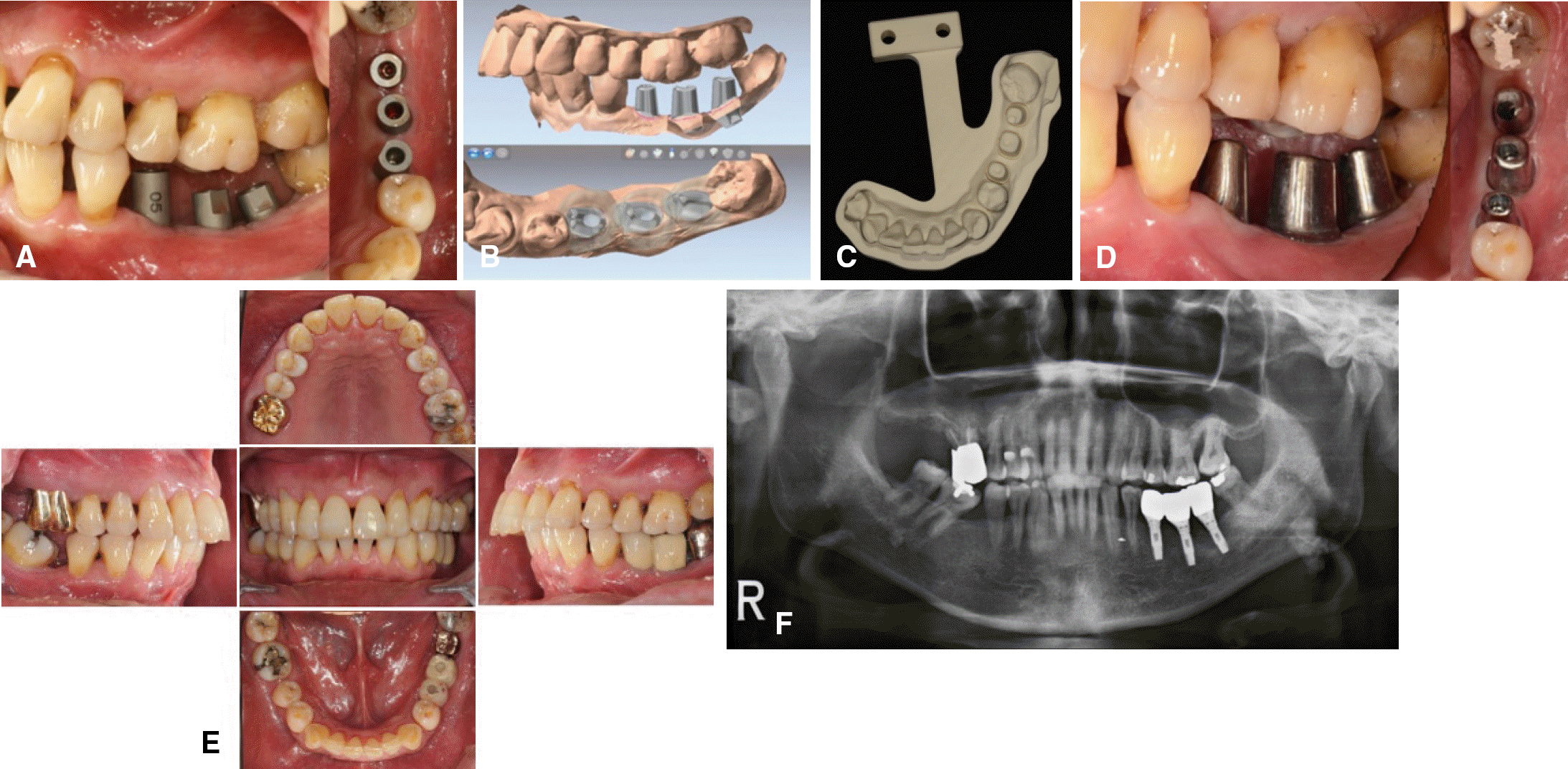
 | Fig. 2.Superstructure fabrication and delivery. (A) Scan bodies were connected and digital intraoral scanning was performed. (B) Customized abutment and working model for final restoration were designed with CAD software. (C) Master model made of polyurethane resin. (D) Customized abutments were tried in the patient' s mouth. (E) Intraoral photos after superstructure delivery. (F) Final panoramic X-ray. |
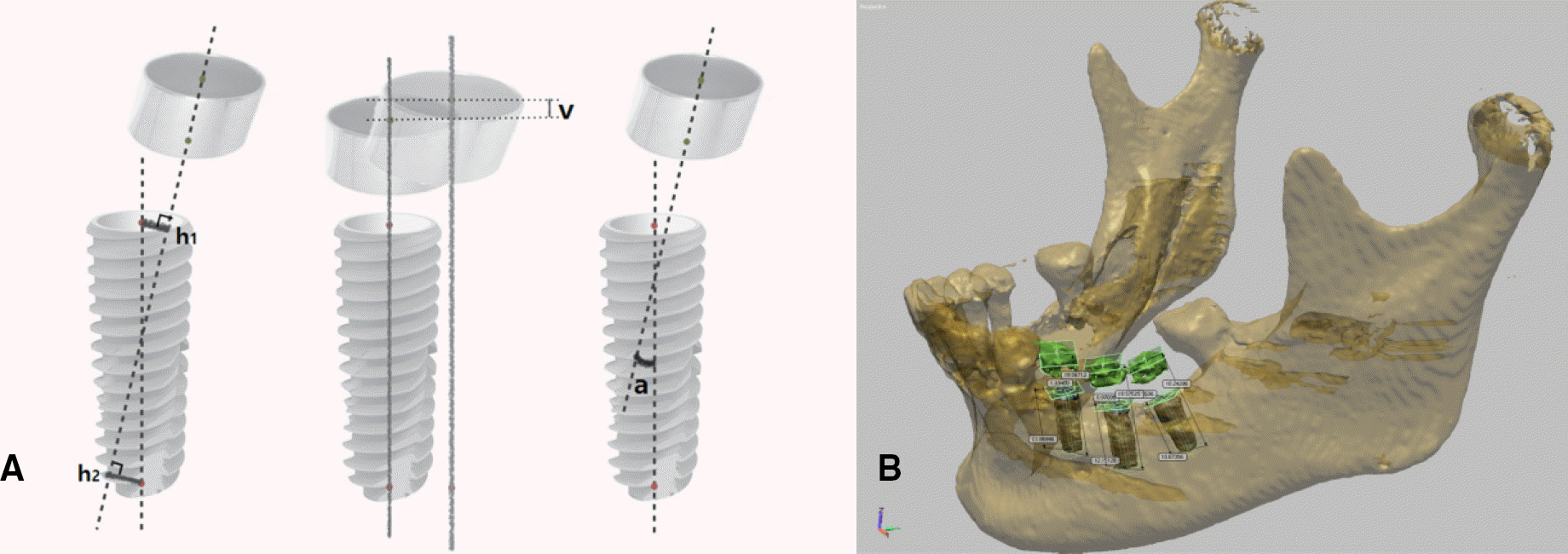
 | Fig. 3.Analysis of errors between vectors of objects.4 (A) Method. (Left) Horizontal error (horizontal distance of the positions of bushings from those planned before surgery, average of h1 and h2); (Center) Vertical error (vertical distance of the positions of bushings from those planned before surgery, v); (Right) Angular error (an angle between a bushing and a stopping, a). (B) Accuracy analysis was done by reverse engineering software. |


 PDF
PDF ePub
ePub Citation
 Print
Print


 XML Download