Abstract
Purpose
In this study, the diameter of each implant driver was measured and compared to find out the compatibility of implant drivers.
Materials and methods
Drivers from 12 implant systems being used in Dankook University Dental Hospital were included in this study. The shapes of the implant drivers were segregated, and the effective length and the diameter of upper, middle, lower part of driver tips were measured (n=10). The measured data were mathematically analyzed for its compatibility.
Results
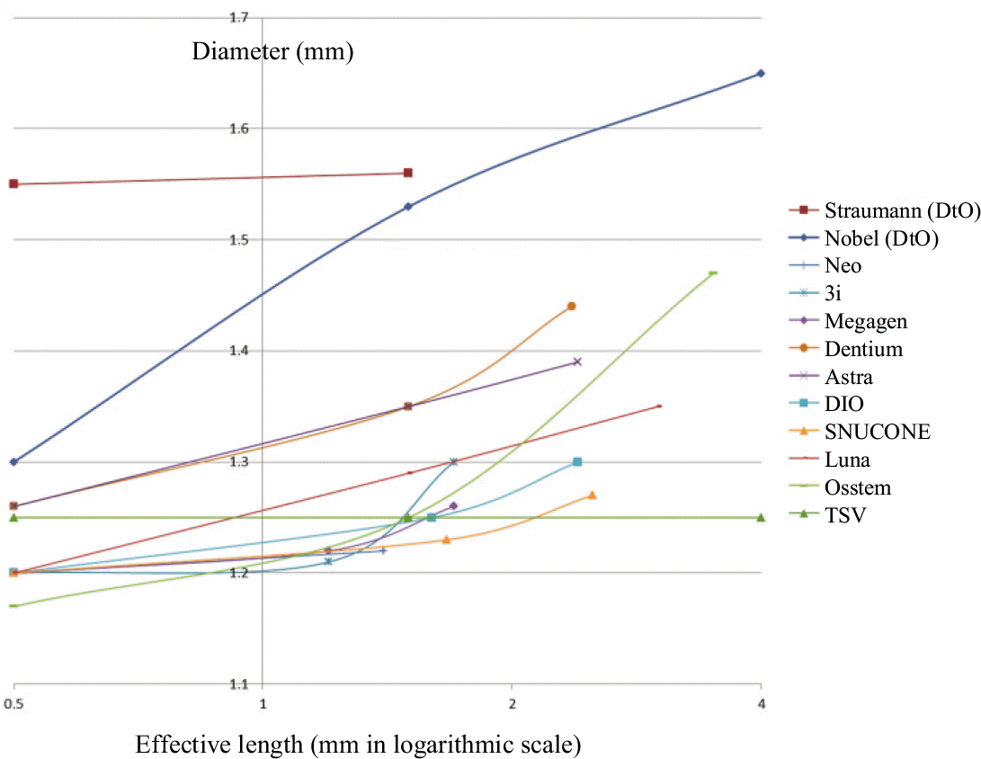
A driver with the smallest diameter (1.17 mm) had the highest compatibility at the upper part of driver tip. This driver could be used for a bigger driver up to 1.35 mm in diameter. There were several driver groups which had the same diameter so as to be interchangeable each other. In the middle part, the smallest diameter measured was 1.2 mm and this was able to replace a driver up to 1.40 mm diameter. Since the diameter generally became thicker from upper part (the tip of driver) to the lower part (the shank of driver), some drivers with bigger diameter at the upper part so which was failed to show any compatibility became compatible with a driver which had smaller diameter at the upper part but wider in the middle part. The compatibility of torx shape drivers were affected by the inner diameter of the drivers not only by the outer diameter. Furthermore, the inner diameter of torx drivers decided the compatibility between torx and hex drivers.
Conclusion
From the study it was found that compatibility in drivers existed among certain implant systems and to check its compatibility the diameter at a certain effective length should be measured. However, there has been not enough studies about long-term use of compatible drivers, so effects of using compatible drivers on drivers and implants are unknown. Therefore, usage in inevitable cases only is recommended and further study is needed. (J Korean Acad Prosthodont 2014;52:34-41)
Go to : 
REFERENCES
1.Bra�nemark PI. Osseointegration and its experimental back ground. J Prosthet Dent. 1983. 50:399–410.
2.Pjetursson BE., Karoussis I., Bu¨rgin W., Bra¨gger U., Lang NP. Patients' satisfaction following Implant therapy. A 10-year prospective cohort study. Clin Oral Implants Res. 2005. 16:185–93.

3.Hoyer SA., Stanfod CM., Burabndham S., Fidrich T., Wagner J., Gratton D. Dynamic fatigue properties of the dental implant-abutment interface: joint opening in wide-diameter versus standard-diameter hex-type implants. J Prosthet Dent. 2001. 85:599–607.

4.Patterson EA., John RB. Theoretical analysis of the fatigue life of fixture screws in osseointegrated Dental implants. Int J Oral Maxillofac Implants. 1992. 7:26–33.
5.Goodacre CJ., Bernal G., Rungcharassaeng K., Kan JY. Clinical complications with implants and implant prostheses. J Prosthet Dent. 2003. 90:121–32.

6.Ekeldt A., Carlsson GE., Bo¨rjesson G. Clinical evaluation of single-tooth restorations supported by osseointegrated implants: a retrospective study. Int J Oral Maxillofac Implants. 1994. 9:179–83.
7.Andersson B., Odman P., Lindvall AM., Lithner B. Single-tooth restorations supported by osseointegrated implants: results and experiences from a prospective study after 2 to 3 years. Int J Oral Maxillofac Implants. 1995. 10:702–11.
8.Jemt T., Pettersson P. A 3-year follow-up study on single implant treatment. J Dent. 1993. 21:203–8.

9.Jemt T., Laney WR., Harris D., Henry PJ., Krogh PH Jr., Polizzi G., Zarb GA., Herrmann I. Osseointegrated implants for single tooth replacement: a 1-year report from a multicenter prospective study, Int J Oral Maxillofac Implants. 1996. 29–36.
10.Kim SK. The effects of the design of abutment screw driver on the amount of time for insertion of screw driver into abutment screw head. J Koean Acad Prosthodont. 2005. 43:258–63.
Go to : 
 | Fig. 1.Various shapes of the implant driver tips. A: torx, B: hexagon, C: minus, D: Square. |
 | Fig. 2.Schematic drawing of driver size measuring points (longitudinal view). E: Effective length. Up: Upper part of the driver tip, M: Middle part of the driver tip, Lw: Lower part of the driver tip. |
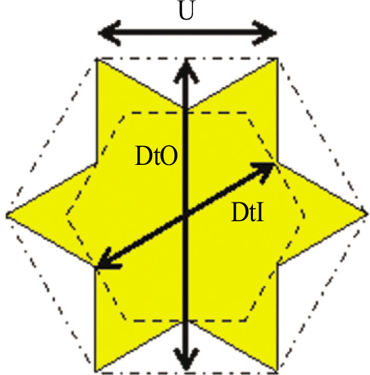
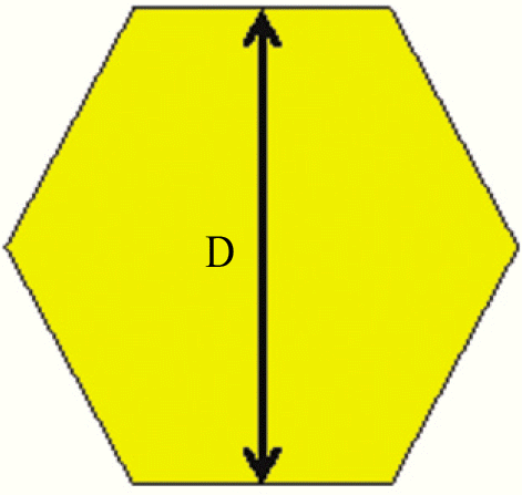 | Fig. 4.Torx driver (cross section). U: Imaginary line between two torx tips, DtO: Measured imaginary hexagon diameter. Outer diameter of torx, DtI: Measured imaginary hexagon diameter. Inner diameter of torx. |
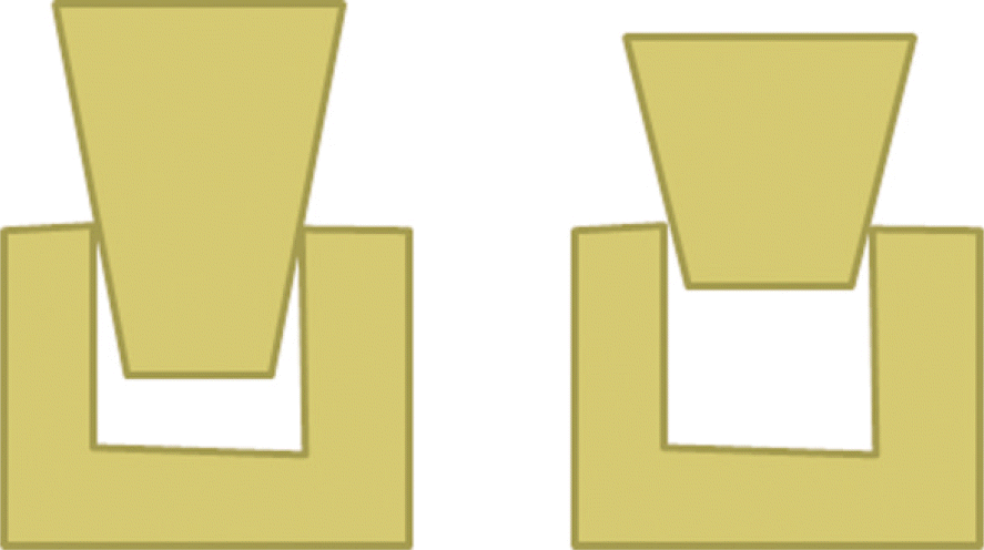 | Fig. 5.Schematic drawing shows compatibility of two drivers with different effective length and size but compatible at certain locations (longitudinal section). |
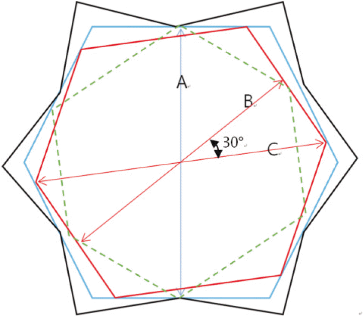 | Fig. 6.Schematic drawing of compatible drivers with different shape and/or diameters (cross section). A: Diameter of large hexagon (blue line), internal diameter of torx (black line), B: Diameter of small hexagon (red line), C: External diameter of small hexagon (red line). A hexagon driver (blue line) of which diameter (A) fits with the internal diameter (A) of a torx driver (black line) can replace the torx driver. A Smaller hexagon driver (red line) can replace a larger hexagon driver (blue line) or a torx driver (black line) when its outer diameter (hexagon tip to tip: C) is larger than the diameter of the targeting hexagon driver (A) or the internal diameter of the torx driver (A); however when its outer diameter is same or smaller than them, the smaller driver (green dotted line) cannot replace the targeting drivers. The angle between B and C is 30° . |
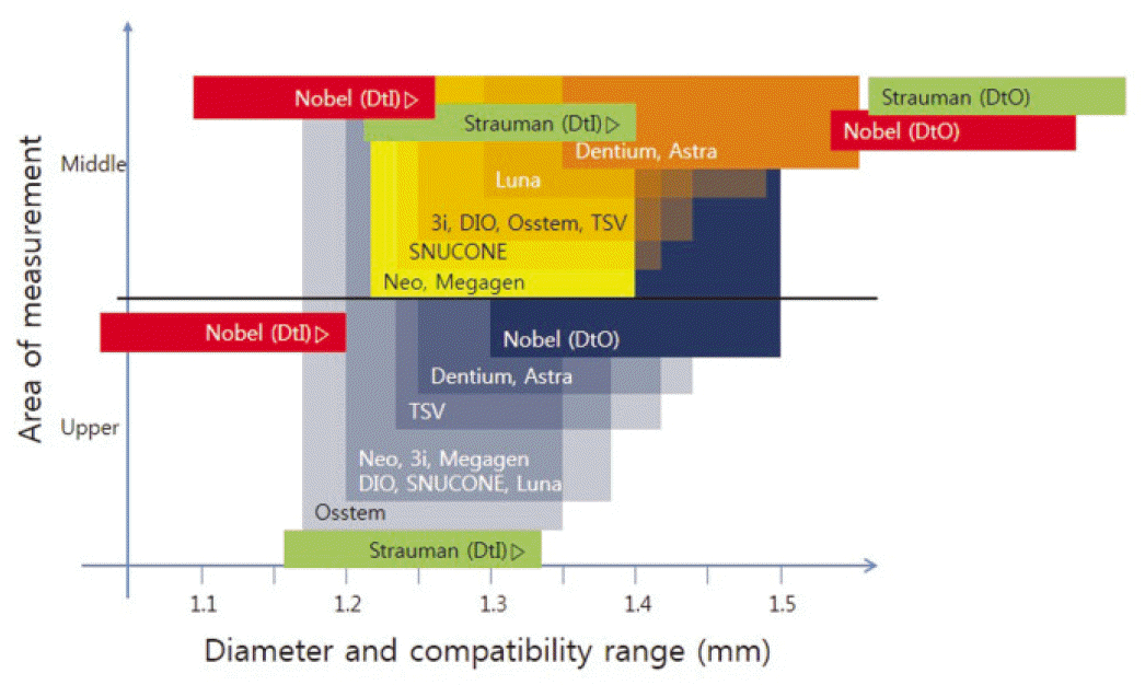 | Fig. 8.Compatibility table of upper (≤0.5 mm) and middle (1.2-1.5 mm). Left border of each box is the diameter of a driver except DtI of Nobel and Straumann (right border), and the width indicates compatibility range. The overlapped parts of smaller diameter driver boxes show these drivers can replace covered larger drivers. Compatibility of the lower parts was practically invalid and not presented. |
Table 1.
Driver information included in this study
Table 2.
Means and Standard deviations of the driver measurements (mm) in the order of effective length


 PDF
PDF ePub
ePub Citation
 Print
Print


 XML Download