Abstract
Purpose
To evaluate the axial displacement of implant-abutment assembly after cyclic loading in internal tapered connection system.
Materials and methods
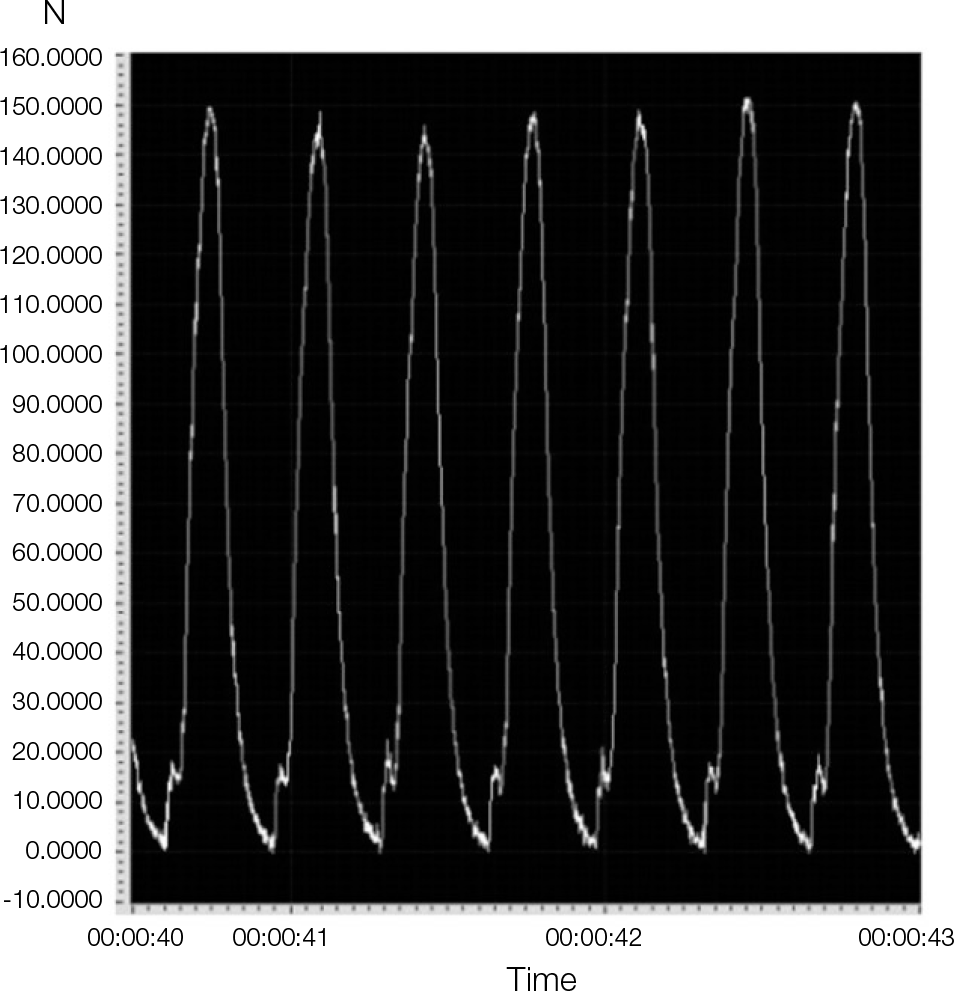
External butt-joint connection implant and internal tapered connection implant were connected with three types of abutment for cement-retained prostheses, i.e. external type abutment (Ext group), internal tapered 1-piece abutment (Int-1 group), and internal tapered 2-piece abutment (Int-2 group). For each group, 7 implants and abutments were used. The implant-abutments assemblies were clamped into the implant holder for vertical loads. A dynamic cyclic loading was applied for 150 ± 10 N at a frequency of 4 Hz. The amount of axial displacement of the abutment into the implant was calculated at each cycle of 0, 5, 10, 50, 100, 1,000, 5,000, and 10,000. A repeated measures analysis of variance (ANOVA) for the overall effect of cyclic loading and the pattern analysis by linear mixed model were used for statistical analysis. Differences at P<.05 were considered statistically significant.
Results
The mean axial displacement after 10,000 cycles were 0.714 ± 0.488 ㎛ in Ext group, 5.286 ± 1.604 ㎛ in Int-1 group, and 11.429 ± 1.902 ㎛ in Int-2 group. In the pattern analysis, Int-1 and Int-2 group showed continuous axial displacement at 10,000 cycles. There was no declining pattern of axial displacement in the Ext group.
Conclusion
The pattern of linear mixed model in Ext group showed no axial displacement. There were continuous axial displacements in abutment-implant assemblies in the Int-1 and Int-2 group at 10,000 cycles. More axial displacement was found in Int-2 group than in Int-1 group. (J Korean Acad Prosthodont 2013;51:315-22)
Go to : 
REFERENCES
1.Jemt T. Fixed implant-supported prostheses in the edentulous maxilla. A five-year follow-up report. Clin Oral Implants Res. 1994. 5:142–7.

2.Buser D., Mericske-Stern R., Bernard JP., Behneke A., Behneke N., Hirt HP., Belser UC., Lang NP. Long-term evaluation of non-submerged ITI implants. Part 1: 8-year life table analysis of a prospective multi-center study with 2359 implants. Clin Oral Implants Res. 1997. 8:161–72.

3.Nelson K., Semper W., Hildebrand D., Ozyuvaci H. A retrospective analysis of sandblasted, acid-etched implants with reduced healing times with an observation period of up to 5 years. Int J Oral Max Impl. 2008. 23:726–32.
4.Goodacre CJ., Bernal G., Rungcharassaeng K., Kan JY. Clinical complications with implants and implant prostheses. J Prosthet Dent. 2003. 90:121–32.

5.Jemt T., Pettersson P. A 3-year follow-up study on single implant treatment. J Dent. 1993. 21:203–8.

6.Sutter F., Weber HP., Sorensen J., Belser U. The New Restorative Concept of the ITI Dental Implant System: Design and Engineering. Int J Periodont Rest. 1993. 13:408–31.
7.Norton MR. Assessment of cold welding properties of the internal conical interface of two commercially available implant systems. J Prosthet Dent. 1999. 81:159–66.
8.Khraisat A., Stegaroiu R., Nomura S., Miyakawa O. Fatigue resistance of two implant/abutment joint designs. J Prosthet Dent. 2002. 88:604–10.

9.Merz BR., Hunenbart S., Belser UC. Mechanics of the implant-abutment connection: An 8-degree taper compared to a butt joint connection. Int J Oral Max Impl. 2000. 15:519–26.
10.Kitagawa T., Tanimoto Y., Odaki M., Nemoto K., Aida M. Influence of implant/abutment joint designs on abutment screw loosening in a dental implant system. J Biomed Mater Res B Appl Biomater. 2005. 75B:457–63.

11.Norton MR. An in vitro evaluation of the strength of an internal conical interface compared to a butt joint interface in implant design. Clin Oral Implants Res. 1997. 8:290–8.

13.Bozkaya D., Muftu S. Mechanics of the tapered interference fit in dental implants. J Biomech. 2003. 36:1649–58.

14.Dailey B., Jordan L., Blind O., Tavernier B. Axial Displacement of Abutments into Implants and Implant Replicas, with the Tapered Cone-Screw Internal Connection, as a Function of Tightening Torque. Int J Oral Max Impl. 2009. 24:251–6.
15.Kim KS., Lim YJ., Kim MJ., Kwon HB., Yang JH., Lee JB., Yim SH. Variation in the total lengths of abutment/implant assemblies generated with a function of applied tightening torque in external and internal implant-abutment connection. Clin Oral Implants Res. 2011. 22:834–9.

16.Lee JH., Kim DG., Park CJ., Cho LR. Axial displacements in external and internal implant-abutment connection. Clin Oral Implants Res. 2012. 1–7.

17.Kim SK., Koak JY., Heo SJ., Taylor TD., Ryoo S., Lee SY. Screw Loosening with Interchangeable Abutments in Internally Connected Implants After Cyclic Loading. Int J Oral Max Impl. 2012. 27:42–7.
18.Richter E-J. In Vivo Vertical Forces on Implants. Int J Oral Max Impl. 1995. 10:120–40.
19.Rosentritt M., Behr M., Gebhard R., Handel G. Influence of stress simulation parameters on the fracture strength of all-ceramic fixed-partial dentures. Dental materials: official publication of the Academy of Dental Materials. 2006. 22:176–82.

20.Bates D., Maechler M., Bolker B. lme4: Linear mixed-effects models using S4 classes. R package version 0.999999-2. http://CRAN.R-project.org/package=lme4. 2013.
21.Siamos G., Winkler S., Boberick KG. Relationship between implant preload and screw loosening on implant-supported prostheses. J Oral Implantol. 2002. 28:67–73.
22.Bakaeen LG., Winkler S., Neff PA. The effect of implant diameter, restoration design, and occlusal table variations on screw loosening of posterior single-tooth implant restorations. J Oral Implantol. 2001. 27:63–72.

23.Wiskott HWA., Nicholls JI., Belser UC. Stress Fatigue: Basic Principles and Prosthodontic Implications. Int J Prosthodont. 1995. 8:105–16.
Go to : 
 | Fig. 1.Custom-made cyclic loading apparatus. A: Cyclic loading machine, ①: motor, ②: cam, ③: weight, ④: height adjusting screw ⑤: impact rod, ⑥: implant holder, B: Implant-abutment assembly was clamped into implant holder (collet and nut). |
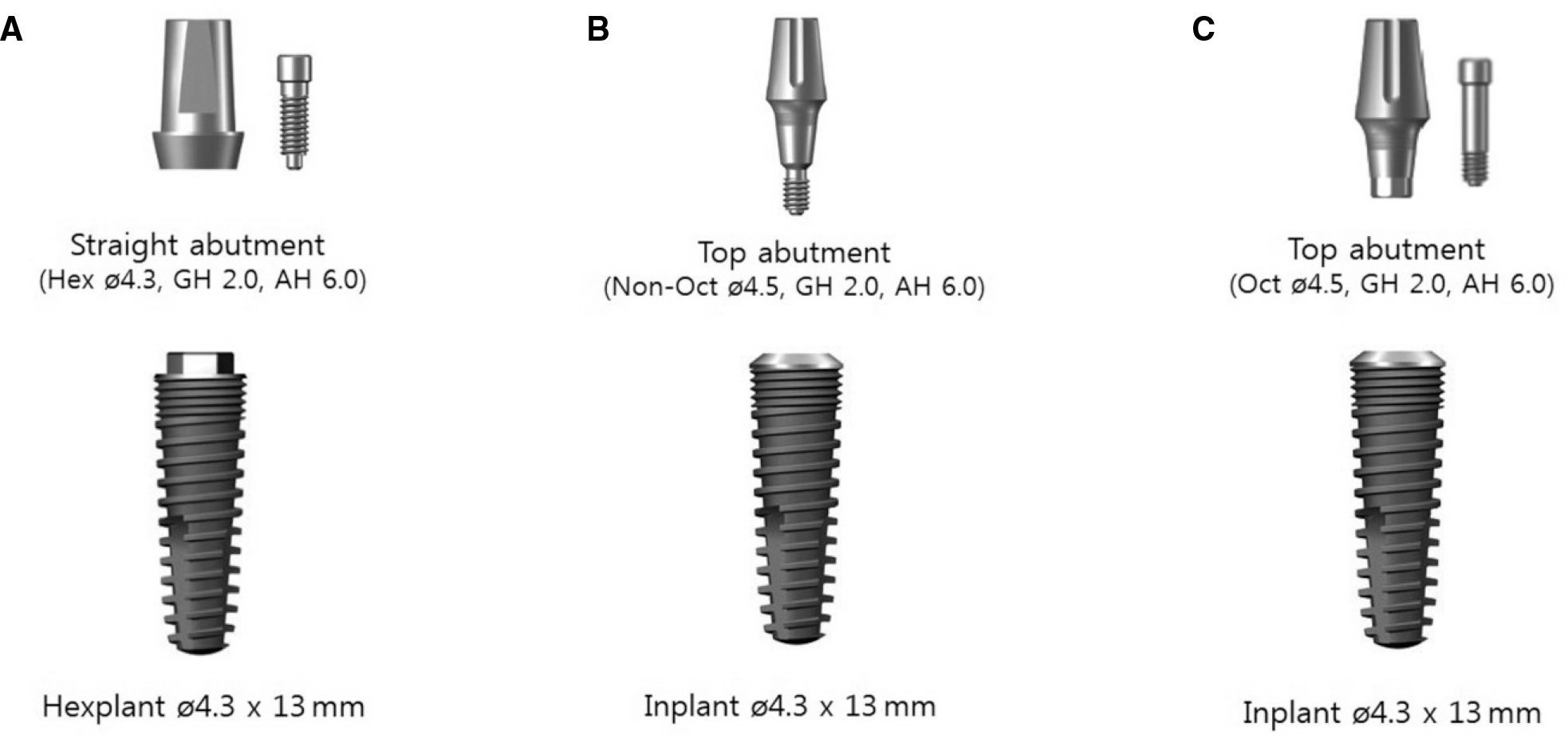 | Fig. 2.This picture shows three groups of implant-abutment assemblies. A: Ext group (left): Straight abutment® was connected to Hexplant® implant, B: Int-1 group (center): 1-piece type Top abutment® (non-octagonal) was connected to Inplant® implant, C: Int-2 group (right): 2-piece type Top abutment® (octagonal) was connected to Inplant® implant. |
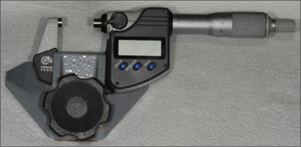
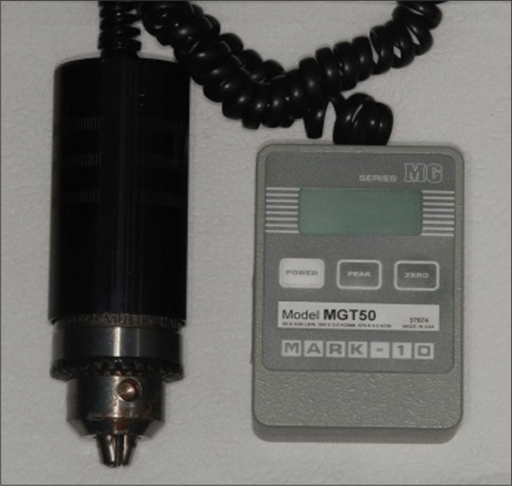 | Fig. 3.Digital torque gauge (MGT50) was used to tighten the abutment into implant at desired torque. |
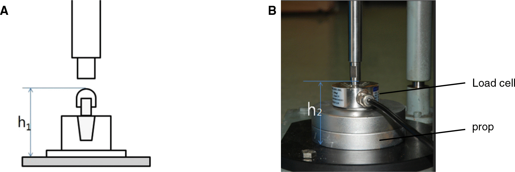 | Fig. 4.Setting the applied load with a load cell. A: Height from metal cap to base of implant holder (h1) was measured for each implant-abutment assembly, B: The prop was adjusted for the load cell to be the same height (h1 = h2). |
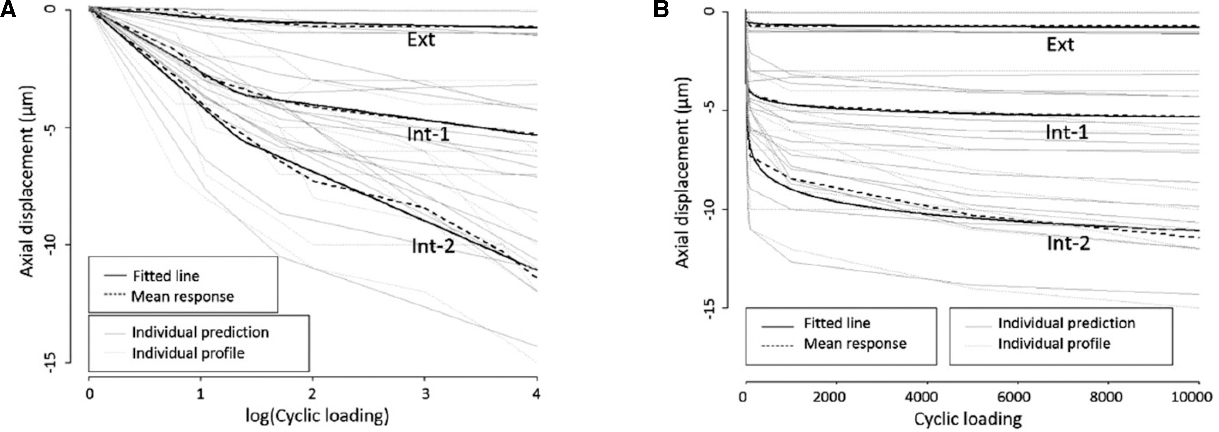 | Fig 7.The patterns of axial displacement of each group with linear mixed models. A: fitted models of axial displacement in logarithmic scale, B: fitted models of axial displacement in original values. |
Table 1.
Implant and abutment systems used in this study (7 samples per group)
Table 2.
Mean (SD) axial displacement of implant-abutment samples at each cycles (㎛)
Table 3.
The patterns of axial displacement with a breakpoint at 1.35 in logarithmic scale


 PDF
PDF ePub
ePub Citation
 Print
Print


 XML Download