Abstract
Purpose
The purpose of this study was to find an inclination slope of the screw thread that is favorable in distributing the stresses to alveolar bone by using three dimensional finite element analysis.
Materials and methods
Three types modelling changed implant thread with fixed pitch of 0.8 mm is the single thread implant with 3.8 inclination, double thread implant with 7.7 inclination and the triple thread implant with 11.5 inclination. And three types implant angulation is the 0, 10 and 15 on alveolar bone. The 9 modelling fabricated for three dimensional finite element analysis that restored prosthesis crown. The crown center applied on 200 N vertical load and 15 tilting load.
Results
1. The more tilting of implant angulation, the more Von-Mises stress and Max principal stress is increasing. 2. Von-Mises stress and Max principal stress is increasing when applied 15 tilting load than vertical load on the bone. 3. When the number of thread increased, the amount of Von-Mises stress, Max principal stress was reduced since the generated stress was effectively distributed. 4. Since the maximum principal stress affects on the alveolar bone can influence deeply on the longevity of the implants. When comparing the magnitude of the maximum principal stress, the triple thread implant had a least amount of stress. This shows that the triple thread implant gave a best result.
Conclusion
A triple thread implant to increase in the thread slope inclination and number of thread is more effective on the distribution of stress than the single and double thread implants especially, implant angulation is more tilting than 10 on alveolar bone. Thus, effective combination of thread number and thread slope inclination can help prolonging the longevity of implant. (J Korean Acad Prosthodont 2013;51:1-10)
Go to : 
REFERENCES
1.Branemark PI. Osseointegration and its experimental background. J Prosthet Dent. 1983. 50:399–410.

2.Adell R., Lekholm U., Rockler B., Branemark PI. A 15-year study of osseointegrated implants in the treatment of the edentulous jaw. Int J Oral Surg. 1981. 10:387–416.

3.Skalak R. Biomechanical considerations in osseointegrated prostheses. J Prosthet Dent. 1983. 49:843–8.

4.Holmes DC., Grigsby WR., Goel VK., Keller JC. Comparison of stress transmission in the IMZ implant system with polyoxymethylene or titanium intramobile element: a finite element stress analysis. Int J Oral Maxillofac Implants. 1992. 7:450–8.
5.Brunski JB. Biomaterials and biomechanics in dental implant design. Int J Oral Maxillofac Implants. 1988. 3:85–97.
6.Rangert B., Jemt T., Jo¨rneus L. Forces and moments on Branemark implants. Int J Oral Maxillofac Implants. 1989. 4:241–7.
7.Holmgren EP., Seckinger RJ., Kilgren LM., Mante F. Evaluating parameters of osseointegrated dental implants using finite element analysis-a two-dimensional comparative study examining the effects of implant diameter, implant shape, and load direction. J Oral Implantol. 1998. 24:80–8.

8.Hoshaw SJ., Brunski JB., Cochran GVB. Mechanical loading of Branemark implants affects interfacial bone modeling and remodeling. Int J Oral Maxillofac Implants. 1994. 9:345–60.
9.Isidor F. Loss of osseointegration caused by occlusal load of oral implants. A clinical and radiographic study in monkeys. Clin Oral Implants Res. 1996. 7:143–52.

10.Rieger MR., Adams WK., Kinzel GL. A finite element survey of eleven endosseous implants. J Prosthet Dent. 1990. 63:457–65.

11.Siegele D., Soltesz U. Numerical investigations of the influence of implant shape on stress distribution in the jaw bone. Int J Oral Maxillofac Implants. 1989. 4:333–40.
12.Holmes DC., Loftus JT. Influence of bone quality on stress distribution for endosseous implants. J Oral Implantol. 1997. 23:104–11.
13.Bergman B. Evaluation of the results of treatment with os-seointegrated implants by the Swedish National Board of Health and Welfare. J Prosthet Dent. 1983. 50:114–5.

14.Bidez MW., Chen Y., McLoughlin SW., English CE. Finite element analysis of four-abutment Hader bar designs. Implant Dent. 1993. 2:171–6.

15.Borchers L., Reichart P. Three-dimensional stress distribution around a dental implant at different stages of interface development. J Dent Res. 1983. 62:155–9.

16.Papavasiliou G., Kamposiora P., Bayne SC., Felton DA. Three-dimensional finite element analysis of stress-distribution around single tooth implants as a function of bony support, prosthesis type, and loading during function. J Prosthet Dent. 1996. 76:633–40.

Go to : 
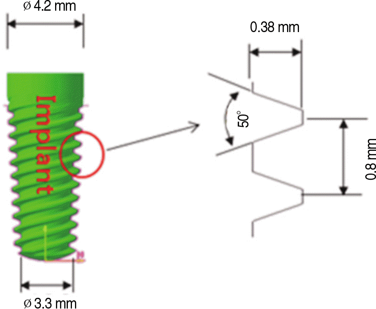
 | Fig. 1.The model of the implant has the 0.8 mm pitch, 0.38 mm spiral ridge and 50° thread angle of a screw in the finite element model. |
 | Fig. 2.The diagram of the implant has different thread slope and the pitch in three types that is the single, double, triple threaded screw. |
 | Fig. 3.A: Design and dimension of restored prosthesis that cervical - occlusal is 8.5 mm and buccolingual is 7.5 mm according to Wheeler's dental anatomy, physiology and occlusion, B: Schematic drawing of the different implant angulation that is 0°, 10° and 15° in a bone. |
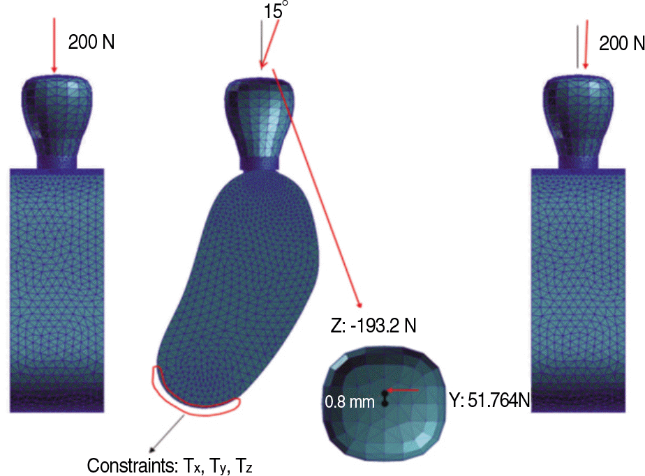
 | Fig. 4.The finite element model with meshing of 200 N vertical load and 15° tilting load applied on the crown center. |
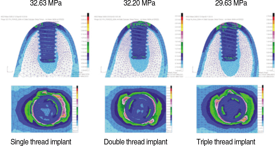
 | Fig. 5.Von-Mises stress in the alveolar bone under the 200 N vertical load was applied when the implant angulation is 0 . |
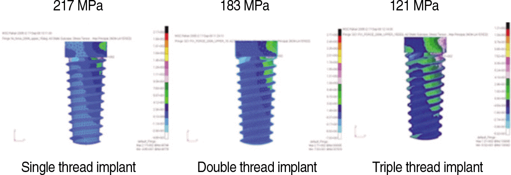
 | Fig. 6.Maximum principal stress in the implant under the 200 N vertical load was applied when the implant angulation is 15° . |
 | Fig. 7.Maximum principal stress in the implant under the 200 N of 15° tilting load was applied when the implant angulation is 0° . |
 | Fig. 8.Maximum principal stress in the implant under the 200 N of 15° tilting load was applied when the implant angulation is 15° . |
Table 1.
Material properties
Table 2.
Number of elements and nodes in finite element models
Table 3.
Von-Mises stress of the different implant types and implant angulation with 200 N vertical load (MPa)
Table 4.
Maximum principal stress of the different implant types and implant angulation with 200 N vertical load (MPa)
Table 5.
Von-Mises stress of the different implant types and implant angulation with 200 N of 15° tilting load (MPa)
Table 6.
Maximum principal stress of the different implant types and implant angulation with 200 N of 150 tilting load (MPa)


 PDF
PDF ePub
ePub Citation
 Print
Print


 XML Download