Abstract
There are still many limitations on fabricating dentures using digital method while computerized production of fixed prostheses utilizing intraoral scanner and CAD/CAM technology has propagated rapidly. Recently the digital solution of fabricating removable partial denture by applying haptic input device, electronic surveying, and rapid prototyping was introduced. In this case presentation, five patients were treated with surveyed crown and removable partial dentures by this digital solution. Fit of dentures was excellent except for one case which showed morphological difference between the actual teeth and that of master cast by the erroneous impression process. There also was not any problem of stability and retention after adaptation in the clinical setting. (J Korean Acad Prosthodont 2011;49:354-61)
Go to : 
REFERENCES
1.Fasbinder DJ. Clinical performance of chairside CAD/CAM restorations. J Am Dent Assoc. 2006. 137:22S–31S.

2.Syrek A., Reich G., Ranftl D., Klein C., Cerny B., Brodesser J. Clinical evaluation of all-ceramic crowns fabricated from intraoral digital impressions based on the principle of active wavefront sampling. J Dent. 2010. 38:553–9.

3.Han J., Wang Y., Lu¨ P. A preliminary report of designing removable partial denture frameworks using a specifically developed software package. Int J Prosthodont. 2010. 23:370–5.
4.Eggbeer D., Bibb R., Williams R. The computer-aided design and rapid prototyping fabrication of removable partial denture frameworks. Proc Inst Mech Eng H. 2005. 219:195–202.

5.Williams RJ., Bibb R., Rafik T. A technique for fabricating patterns for removable partial denture frameworks using digitized casts and electronic surveying. J Prosthet Dent. 2004. 91:85–8.

6.Williams RJ., Bibb R., Eggbeer D., Collis J. Use of CAD/CAM technology to fabricate a removable partial denture framework. J Prosthet Dent. 2006. 96:96–9.

7.Williams RJ., Bibb R., Eggbeer D. CAD/CAM in the Fabrication of Removable Partial Denture Frameworks: A Virtual Method of Surveying 3D Scanned Dental Casts. Quintessence J Dent Technol. 2004. 2:268–76.
8.Bibb RJ., Eggbeer D., Williams RJ., Woodward A. Trial fitting of a removable partial denture framework made using computer-aided design and rapid prototyping techniques. Proc Inst Mech Eng H. 2006. 220:793–7.

9.Pham DT., Gault RS. A comparison of rapid prototyping technologies. Int J Mach Tool Manuf. 1998. 38:1257–87.

10.Yadroitsev I., Bertrand Ph., Smurov I. Parametric analysis of the selective laser melting process. Appl Surf Sci. 2007. 253:8064–9.

11.Kibi M., Ono T., Dong J., Mitta K., Gonda T., Maeda Y. Development of an RPD CAD system with finite element stress analysis. J Oral Rehabil. 2009. 36:442–50.

12.Sun Y., Lu¨ P., Wang Y. Study on CAD&RP for removable complete denture. Comput Methods Programs Biomed. 2009. 93:266–72.
Go to : 
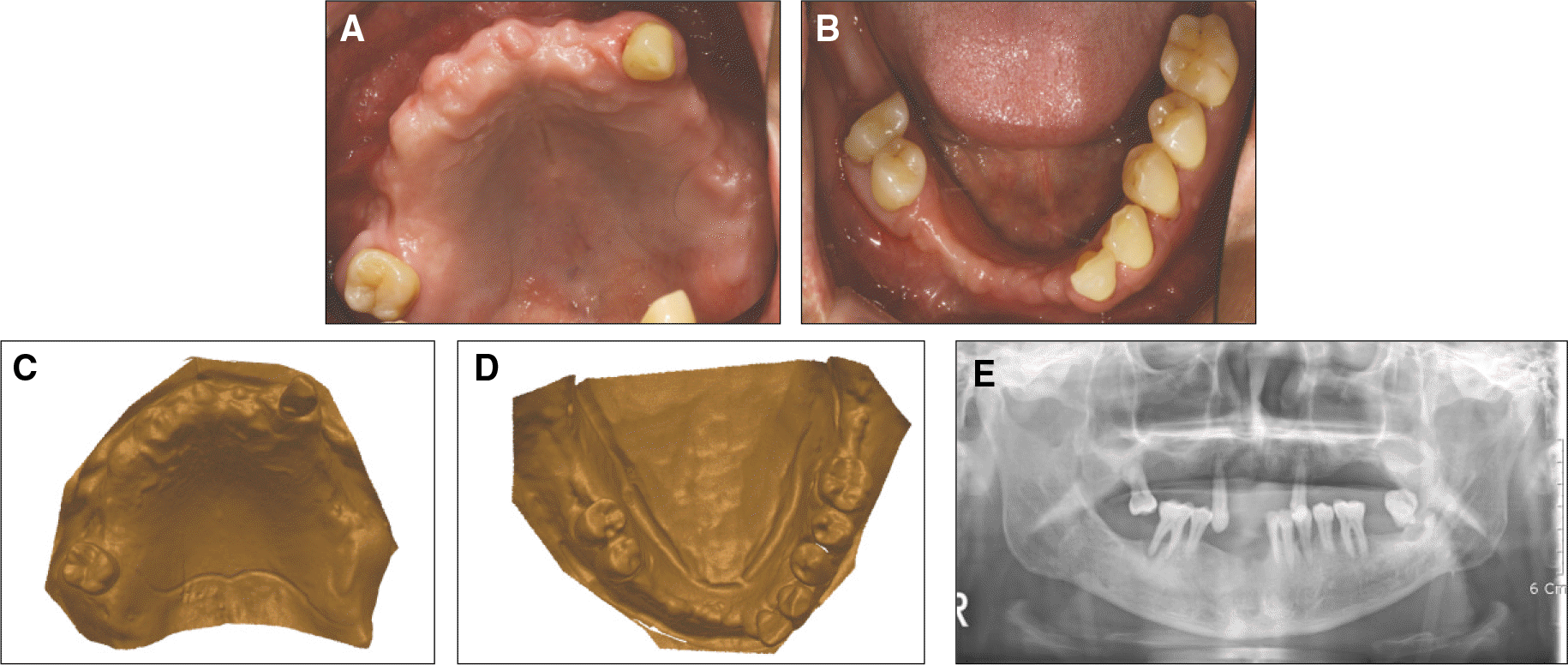
 | Fig. 1.Initial photograph of clinical case 1. A, B: initial occlusal view, C, D: the solid computer model of the patient's cast, E: initial panoramic view. |
 | Fig. 2.Surveyed crown fabrication utilizing electronic surveying. (Case 1) A: clinical photo after hemi-section surgery of lower right first molar, B: after preparation for surveyed restoration, C: electronic view of abutment teeth after setting ‘path of insertion’, D: completed surveyed crown. |
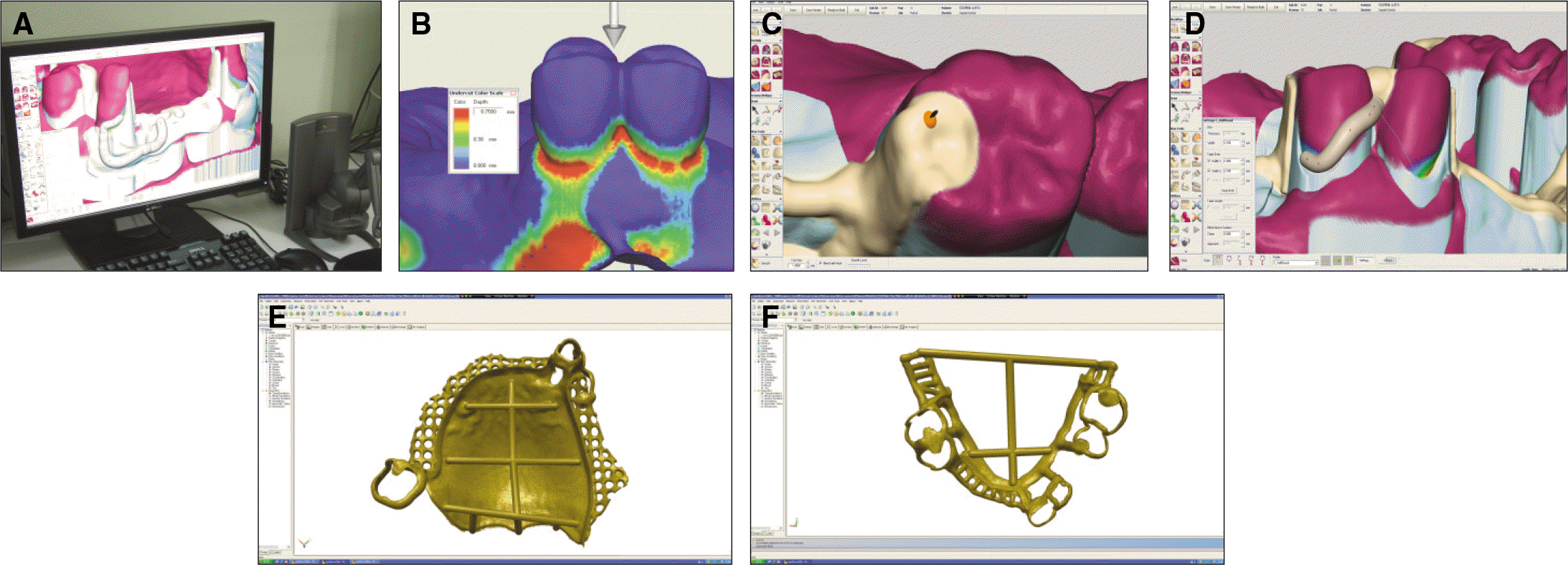
 | Fig. 3.Computer-aided designing procedures of case 1. A: haptic input device and FreeForm CAD software, B: electronic surveying, C: occlusal rest and minor connector designing, D: retentive tip goes below ‘height of contour’ (light blue color) and into the notch (rainbow color) made during electronic surveying, E, F: completed upper and lower framework design with sprue structure for metal casting. |
 | Fig. 4.Framework fit check procedure at patient 1. A: Occlusal view of upper arch, B: framework fits well on lower teeth. |
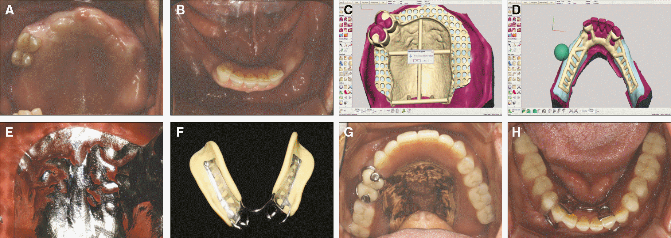
 | Fig. 5.Summarized photographs of case 2. A: the solid computer model of the patient's cast, B: electronic surveying and framework design on FreeForm software, C: completed framework on master cast, D: final prosthesis put on patient's upper arch. |
 | Fig. 6.Summarized photographs of case 3. A: scanning procedure, B: completed framework design, C: framework fit check on master model, D: final prosthesis in the mouth. |


 PDF
PDF ePub
ePub Citation
 Print
Print


 XML Download