Abstract
Purpose
This study aims at investigating the influence of various insertion torques on thermal changes of bone. A proper insertion torque is derived based on the thermal analysis with two different implant designs.
Materials and methods
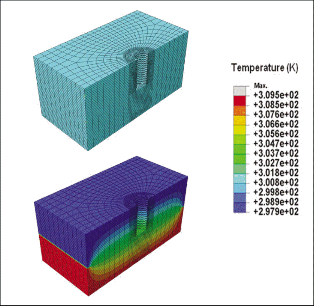
For implant materials, bovine scapula bone of 15 - 20 mm thickness was cut into 35 mm by 40 - 50 mm pieces. Of these, the pieces having 2 - 3 mm thickness cortical bone were used as samples. Then, the half of the sample was immersed in a bath of 36.5℃ and the other half was exposed to ambient temperature of 25℃, so that the inner and surface temperatures reached 36.5℃ and 28℃, respectively. Two types of implants (4.5 × 10 mm Bra®nemark type, 4.8 ×10 mm Microthread type) were inserted into bovine scapula bone and the temperature was measured by a thermocouple at 0.2 mm from the measuring point. Finite element method (FEM) was used to analyze the thermal changes at contacting surface assuming that the sample is a cube of 4 cm ×4 cm × 2 cm and a layer up to 2 mm from the top is cortical bone and below is a cancellous bone. Boundary conditions were set on the basis of the shape of cavity after implants. SolidWorks was used as a CAD program with the help of Abaqus 6.9-1.
Results
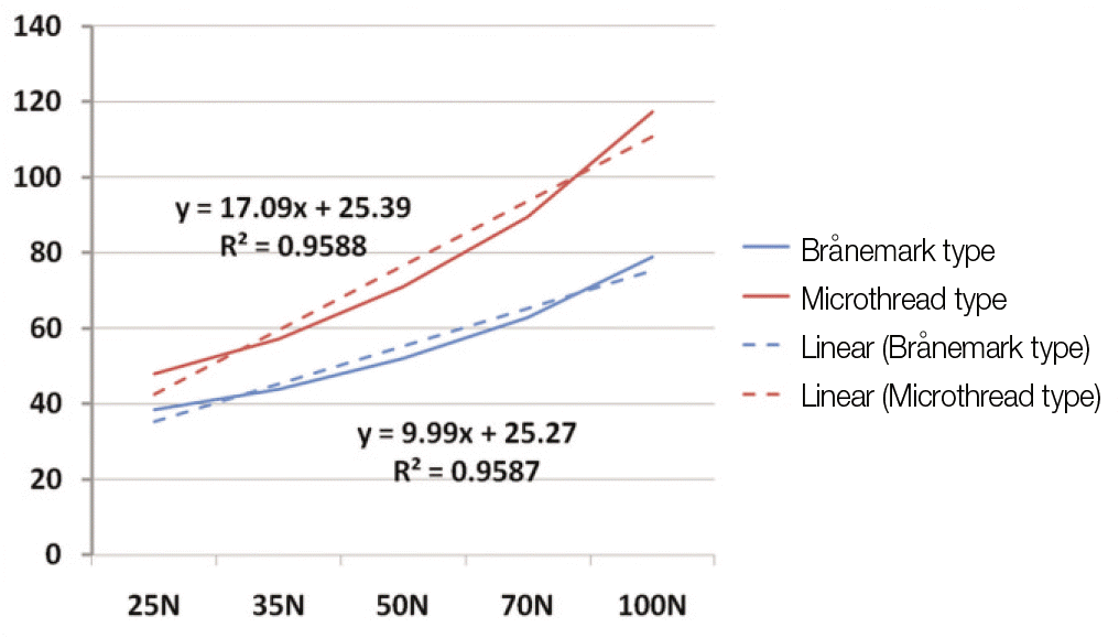
In the in-vitro experiment, the Microhead type implant gives a higher maximum temperature than that of the Bra®nemark type, which is attributed to high frictional heat that is associated with the implant shape. In both types, an Eriksson threshold was observed at torques of 50 Ncm (Bra®nemark type) and 35 Ncm (Microthread type), respectively. Based on these findings, the Microthread type implant is more affected by insertion torques.
Conclusion
This study demonstrate that a proper choice of insertion torque is important when using a specific type of implant. In particular, for the Microthread type implant, possible bone damage may be expected as a result of frictional heat, which compensates for initial high success rate of fixation. Therefore, the insertion torque should be adjusted for each implant design. Furthermore, the operation skills should be carefully chosen for each implant type and insertion torque. (J Korean Acad Prosthodont 2011;49:168-76)
Go to : 
REFERENCES
1.Branemark PI., Hansson BO., Adell R., Breine U., Lindstro¨m J., Halle′n O., Ohman A. Osseointegrated implants in the treatment of the edentulous jaw. Experience from a 10-year period. Scand J Plast Reconstr Surg Suppl. 1977. 16:1–132.
2.Adell R., Lekholm U., Rockler B., Branemark PI. A 15-year study of osseointegrated implants in the treatment of the edentulous jaw. Int J Oral Surg. 1981. 10:387–416.

3.Adell R., Lekholm U. Surgical procedures. Zarb GA. Branemark PI, Albrektsson T, editors. Tissue-integrated prostheses: Osseointegration in clinical dentistry. Chicago: Quintessence;Publishing. 1985. p. 1–35.
4.Bass SL., Triplett RG. The effects of preoperative resorption and jaw anatomy on implant success. A report of 303 cases. Clin Oral Implants Res. 1991. 2:193–8.

5.Hutton JE., Heath MR., Chai JY., Harnett J., Jemt T., Johns RB., McKenna S., McNamara DC., van Steenberghe D., Taylor R, et al. Factors related to success and failure rates at 3-year follow-up in a multicenter study of overdentures supported by Branemark implants. Int J Oral Maxillofac Implants. 1995. 10:33–42.
6.Friberg B., Jemt T., Lekholm U. Early failures in 4,641 consecutively placed Branemark dental implants: a study from stage 1 surgery to the connection of completed prostheses. Int J Oral Maxillofac Implants. 1991. 6:142–6.
7.Truhlar RS., Morris HF., Ochi S., Winkler S. Second-stage failures related to bone quality in patients receiving endosseous dental implants: DICRG Interim Report No. 7. Dental Implant Clinical Research Group. Implant Dent. 1994. 3:252–5.
8.Jaffin RA., Berman CL. The excessive loss of Branemark fixtures in type IV bone: a 5-year analysis. J Periodontol. 1991. 62:2–4.

9.Levine RA., Clem DS 3rd., Wilson TG Jr., Higginbottom F., Saunders SL. A multicenter retrospective analysis of the ITI implant system used for single-tooth replacements: preliminary results at 6 or more months of loading. Int J Oral Maxillofac Implants. 1997. 12:237–42.
10.Goodacre CJ., Bernal G., Rungcharassaeng K., Kan JY. Clinical complications with implants and implant prostheses. J Prosthet Dent. 2003. 90:121–32.

11.Eriksson AR., Albrektsson T. Temperature threshold levels for heat-induced bone tissue injury: a vital-microscopic study in the rabbit. J Prosthet Dent. 1983. 50:101–7.

12.Cochran DL., Buser D., ten Bruggenkate CM., Weingart D., Taylor TM., Bernard JP., Peters F., Simpson JP. The use of reduced healing times on ITI implants with a sandblasted and acid-etched (SLA) surface: early results from clinical trials on ITI SLA implants. Clin Oral Implants Res. 2002. 13:144–53.
13.Sutter F., Weber HP., Sorensen J., Belser U. The new restorative concept of the ITI dental implant system. Design and engineering. Int J Periodont Restorative Dent. 1993. 13:409–31.
14.Misch CE. Implant design considerations for the posterior regions of the mouth. Implant Dent. 1999. 8:376–86.

15.Strong JT., Misch CE., Bidez MW., Nalluri P. Functional surface area: thread form and diameter optimization for implant body design. Compendium. 1998. 19:4–9.
16.Norton MR. An in vitro evaluation of the strength of an internal conical interface compared to a butt joint interface in implant design. Clin Oral Implants Res. 1997. 8:290–8.

17.Norton MR. Assessment of cold welding properties of the internal conical interface of two commercially available implant systems. J Prosthet Dent. 1999. 81:159–66.

18.Norton MR. In vitro evaluation of the strength of the conical implant-to-abutment joint in two commercially available implant systems. J Prosthet Dent. 2000. 83:567–71.

19.Fish J., Belytschko T. A first course in finite elements. John Willey & Sons;2007.
21.Davim JP., Marques N. Dynamical experimental study of friction and wear behaviour of bovine cancellous bone sliding against a metallic counterface in a water lubricated environment. J Mater Proc Tech. 2004. 152:389–94.

22.Davidson SR., David F. James. Measurement of thermal conductivity of bovine cortical bone. Med Eng Phys. 2000. 22:741–7.
23.Hosokawa A., Otani T. Ultrasonic wave propagation in bovine cancellous bone. J Acoust Soc Am. 1997. 101:558–62.

24.Esposito M., Hirsch J., Lekholm U., Thomsen P. Differential diagnosis and treatment strategies for biologic complications and failing oral implants: a review of the literature. Int J Oral Maxillofac Implants. 1999. 14:473–90.
25.Esposito M., Thomsen P., Ericson LE., Sennerby L., Lekholm U. Histopathologic observations on late oral implant failures. Clin Implant Dent Relat Res. 2000. 2:18–32.

26.Lundskog J. Heat and bone tissue. An experimental investigation of the thermal properties of bone and threshold levels for thermal injury. Scand J Plast Reconstr Surg. 1972. 9:1–80.
27.Eriksson AR., Albrektsson T. Temperature threshold levels for heat-induced bone tissue injury: a vital-microscopic study in the rabbit. J Prosthet Dent. 1983. 50:101–7.

28.Sevitt S. Local vascular changes in burned skin. Proc R Soc Med. 1954. 47:225–8.
29.O'Sullivan D., Sennerby L., Meredith N. Measurements comparing the initial stability of five designs of dental implants: a human cadaver study. Clin Implant Dent Relat Res. 2000. 2:85–92.
30.Park JH., Lim YJ., Kim MJ., Kwon HB. The effect of various thread designs on the initial stability of taper implants. J Adv Prosthodont. 2009. 1:19–25.

31.Huh JB., Ko SM. The comparative study of thermal inductive effect between internal connection and external connection implant in abutment preparation. J Korean Acad Prosthodont. 2007. 45:60–70.
32.Cho JM., Cho U., Yun MJ., Jeong CM., Jeon YC. Influence of implant diameter and length changes on initial stability J Korean Acad Prosthodont. 2009. 47:335–41.
Go to : 
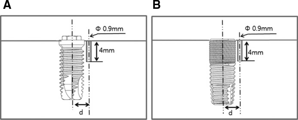 | Fig. 2.Schematic presentation of thermocouple position. A: Bra®nemark type (d = 2.8 ± 0.05), B: Microthread type (d = 3.05 ± 0.05). |
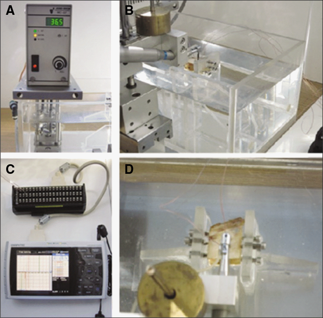 | Fig. 3.
In vitro conditions. A: temperature controller, B: constant temperature bath C: thermocouple and data logger, D: bone drilling procedure. |
 | Fig. 6.Temperature changes with different insertion torques at the Bra®nemark type. A: 25, B: 35, C: 50, D: 75, E: 100 N. |
 | Fig. 7.Temperature changes with different insertion torques at the Microthread type. A: 25, B: 35, C: 50, D: 75, E: 100 N. |
Table 1.
Heat flux according to time and position
| Heat flux | Boundary condition | |
|---|---|---|
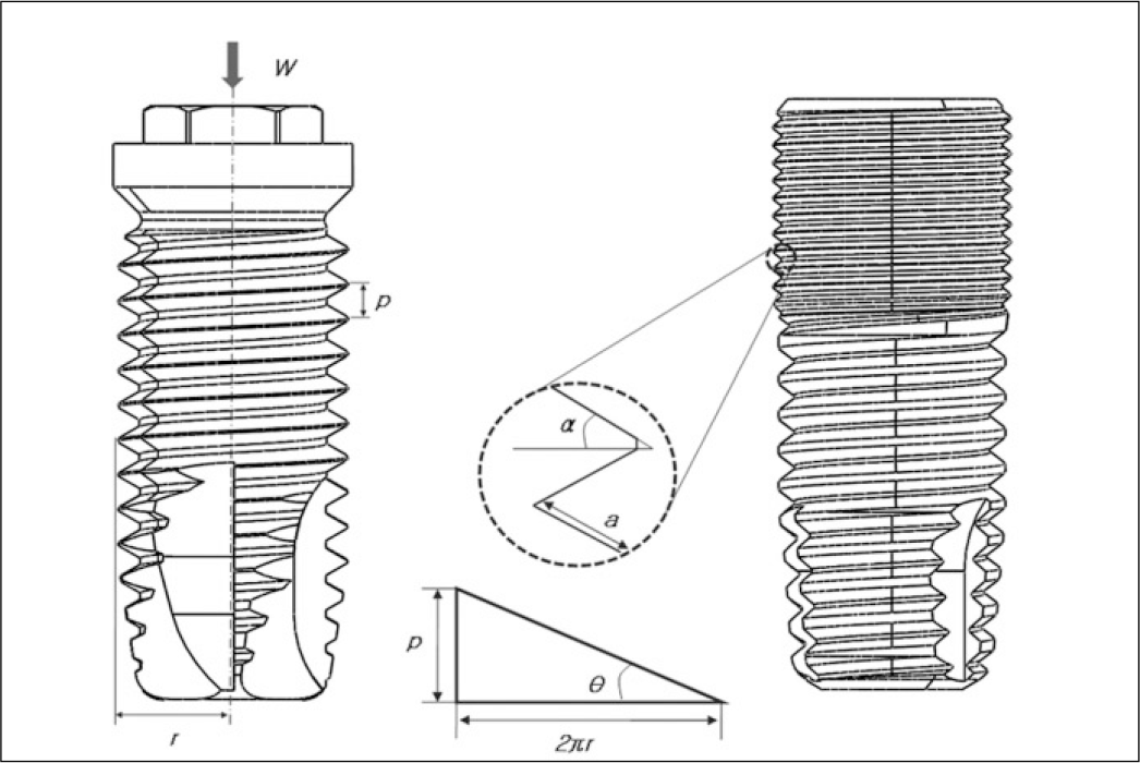
| Upper part condition | Q = μ W×cos θ a×t×cos α | α 60×sin θ Z ≥ 2πr×t×(RPM) |
| Q = 0 | Z < 2πr×t×(RPM) 60×sin θ | |
| Lower part condition | Q = 0 | All area |
W: insertion torque, Q = μ Lv: heat flux, μ : coefficient of kinetic friction, p: pitch of screw thread, r: Implant radius, L: normal force per unit area at screw thread of bone, (RPM): Revolutions per minute of implant, t: time(second), a: width of screw thread, v: linear velocity of a point on implant screw thread.
Table 2.
Maximum temperatures recorded at the 0.2 mm distance with bovin bone (℃)
Table 3.
Maximum temperature throughout simulation (℃)
| Bra®nemark type | Microthread type | |
|---|---|---|
| 25 N | 38.5 | 48 |
| 35 N | 43.9 | 57.3 |
| 50 N | 52 | 71.1 |
| 70 N | 62.8 | 89.6 |
| 100 N | 79 | 117.3 |
Table 4.
Thermal changes of Bra®nemark type implant according to time with sim ulation (at the 0.2 mm distance) (℃
Table 5.
Thermal changes of microthread type implant according to time with simulation (at the 0.2 mm distance) (℃)


 PDF
PDF ePub
ePub Citation
 Print
Print


 XML Download