

 PDF
PDF ePub
ePub Citation
 Print
Print


Abstract
Purpose
The template-guided implant surgery offers several advantages over the traditional approach. The purpose of this study was to evaluate the accuracy of coordinate synchronization procedure with 5-axis milling machine for surgical template fabrication by means of reverse engineering through universal CAD software.
Materials and methods
The study was performed on ten edentulous models with imbedded gutta percha stoppings which were hidden under silicon gingival form. The platform for synchordination was formed on the bottom side of models and these casts were imaged in Cone beam CT. Vectors of stoppings were extracted and transferred to those of planned implant on virtual planning software. Depth of milling process was set to the level of one half of stoppings and the coordinate of the data was synchronized to the model image. Synchronization of milling coordinate was done by the conversion process for the platform for the synchordination located on the bottom of the model. The models were fixed on the synchordination plate of 5-axis milling machine and drilling was done as the planned vector and depth based on the synchronized data with twist drill of the same diameter as GP stopping. For the 3D rendering and image merging, the impression tray was set on the conbeam CT and pre- and post- CT acquiring was done with the model fixed on the impression body. The accuracy analysis was done with Solidworks (Dassault systems, Concord, USA) by measuring vector of stopping's top and bottom centers of experimental model through merging and reverse engineering the planned and post-drilling CT image. Correlations among the parameters were tested by means of Pearson correlation coefficient and calculated with SPSS (release 14.0, SPSS Inc. Chicago, USA) (α= 0.05).
Results
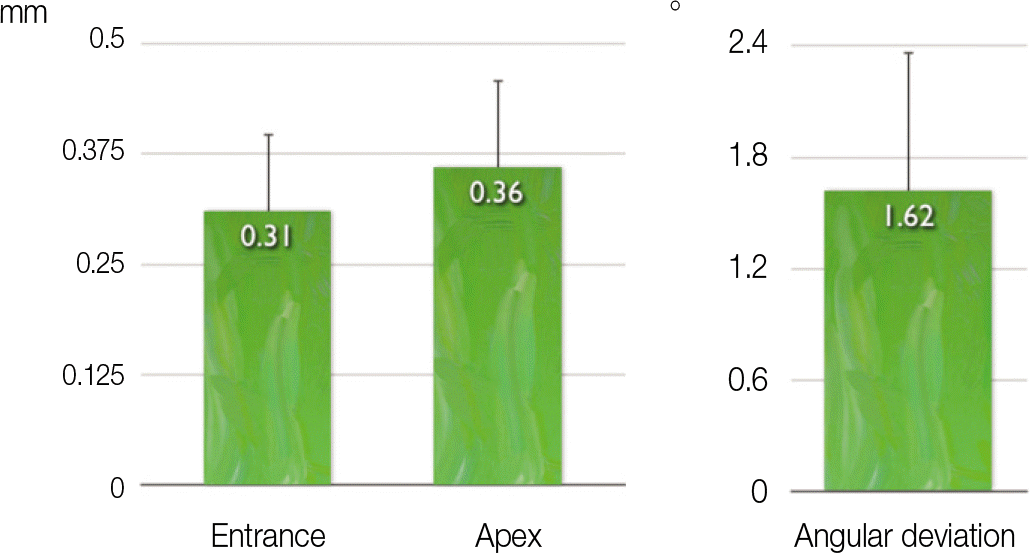
Due to the declination, GP remnant on upper half of stoppings was observed for every drilled bores. The deviation between planned image and drilled bore that was reverse engineered was 0.31 (0.15 - 0.42) mm at the entrance, 0.36 (0.24 - 0.51) mm at the apex, and angular deviation was 1.62 (0.54 - 2.27)° . There was positive correlation between the deviation at the entrance and that at the apex (Pearson Correlation Coefficient = 0.904, P = .013).
Go to : 
REFERENCES
1.Hounsfield GN. Computerized transverse axial scanning (tomography): Part I. Description of system. 1973. Br J Radiol. 1995. 68:H166–72.
2.Jacobs R., Adriansens A., Verstreken K., Suetens P., van Steenberghe D. Predictability of a three-dimensional planning system for oral implant surgery. Dentomaxillofac Radiol. 1999. 28:105–11.

3.Fortin T., Champleboux G., Bianchi S., Buatois H., Coudert JL. Precision of transfer of preoperative planning for oral implants based on conebeam CT-scan images through a robotic drilling machine. Clin Oral Implants Res. 2002. 13:651–6.
4.Fortin T., Champleboux G., Lorme ′e J., Coudert JL. Precise dental implant placement in bone using surgical guides in conjunction with medical imaging techniques. J Oral Implantol. 2000. 26:300–3.
5.Schmitt SM., Chance DA. Fabrication of titanium implant-retained restorations with nontraditional machining techniques. Int J Prosthodont. 1995. 8:332–6.
6.Lee WJ., Hong YS., Lee YH. An Implementation Scheme for Rapid Prototyping Systems. J KSME. 1993. 33:297–310.
7.Lee SH., Chang IT., Yim SH. Dimensional accuracy of denture base using laser scanner of reverse engineering technic. J Korean Acad Prosthodont. 1999. 37:167–84.
8.Valente F., Schiroli G., Sbrenna A. Accuracy of computer-aided oral implant surgery: a clinical and radiographic study. Int J Oral Maxillofac Implants. 2009. 24:234–42.
9.Van Assche N., van Steenberghe D., Guerrero ME., Hirsch E., Schutyser F., Quirynen M., Jacobs R. Accuracy of implant placement based on pre-surgical planning of three-dimensional conebeam images: a pilot study. J Clin Periodontol. 2007. 34:816–21.
10.Hoffmann J., Westendorff C., Gomez-Roman G., Reinert S. Accuracy of navigation-guided socket drilling before implant installation compared to the conventional free-hand method in a synthetic edentulous lower jaw model. Clin Oral Implants Res. 2005. 16:609–14.
11.Eggers G., Patellis E., Mu ¨hling J. Accuracy of template-based dental implant placement. Int J Oral Maxillofac Implants. 2009. 24:447–54.
12.Widmann G., Bale RJ. Accuracy in computer-aided implant surgery-a review. Int J Oral Maxillofac Implants. 2006. 21:305–13.
13.Fortin T., Bosson JL., Isidori M., Blanchet E. Effect of flapless surgery on pain experienced in implant placement using an image-guided system. Int J Oral Maxillofac Implants. 2006. 21:298–304.
14.Fortin T., Bosson JL., Coudert JL., Isidori M. Reliability of preoperative planning of an image-guided system for oral implant placement based on 3-dimensional images: an in vivo study. Int J Oral Maxillofac Implants. 2003. 18:886–93.
15.Naitoh M., Ariji E., Okumura S., Ohsaki C., Kurita K., Ishigami T. Can implants be correctly angulated based on surgical templates used for osseointegrated dental implants? Clin Oral Implants Res. 2000. 11:409–14.
16.Schermeier O., Lueth T., Cho C., Hildebrand D., Klein M., Nelson K. The precision of the RoboDent system- An in vitro study. In: Lemke HU, Vannier MW, Inamura K, Farman AG. Computer-assisted Radiology and Surgery,. New York: Springer;2002. p. 947–52.
17.Worthington P. Injury to the inferior alveolar nerve during implant placement: a formula for protection of the patient and clinician. Int J Oral Maxillofac Implants. 2004. 19:731–4.
18.Ruppin J., Popovic A., Strauss M., Spu ¨ntrup E., Steiner A., Stoll C. Evaluation of the accuracy of three different computer-aided surgery systems in dental implantology: optical tracking vs. stereolithographic splint systems. Clin Oral Implants Res. 2008. 19:709–16.
19.Sarment DP., Sukovic P., Clinthorne N. Accuracy of implant placement with a stereolithographic surgical guide. Int J Oral Maxillofac Implants. 2003. 18:571–7.
Go to :
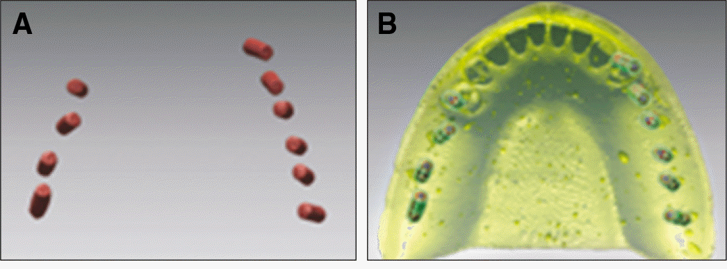 | Fig. 1.3D images of gutta percha stoppings rendered on implant planning software. A: GP cylinders without master cast layer, B: master cast with virtual planning for guided template. |
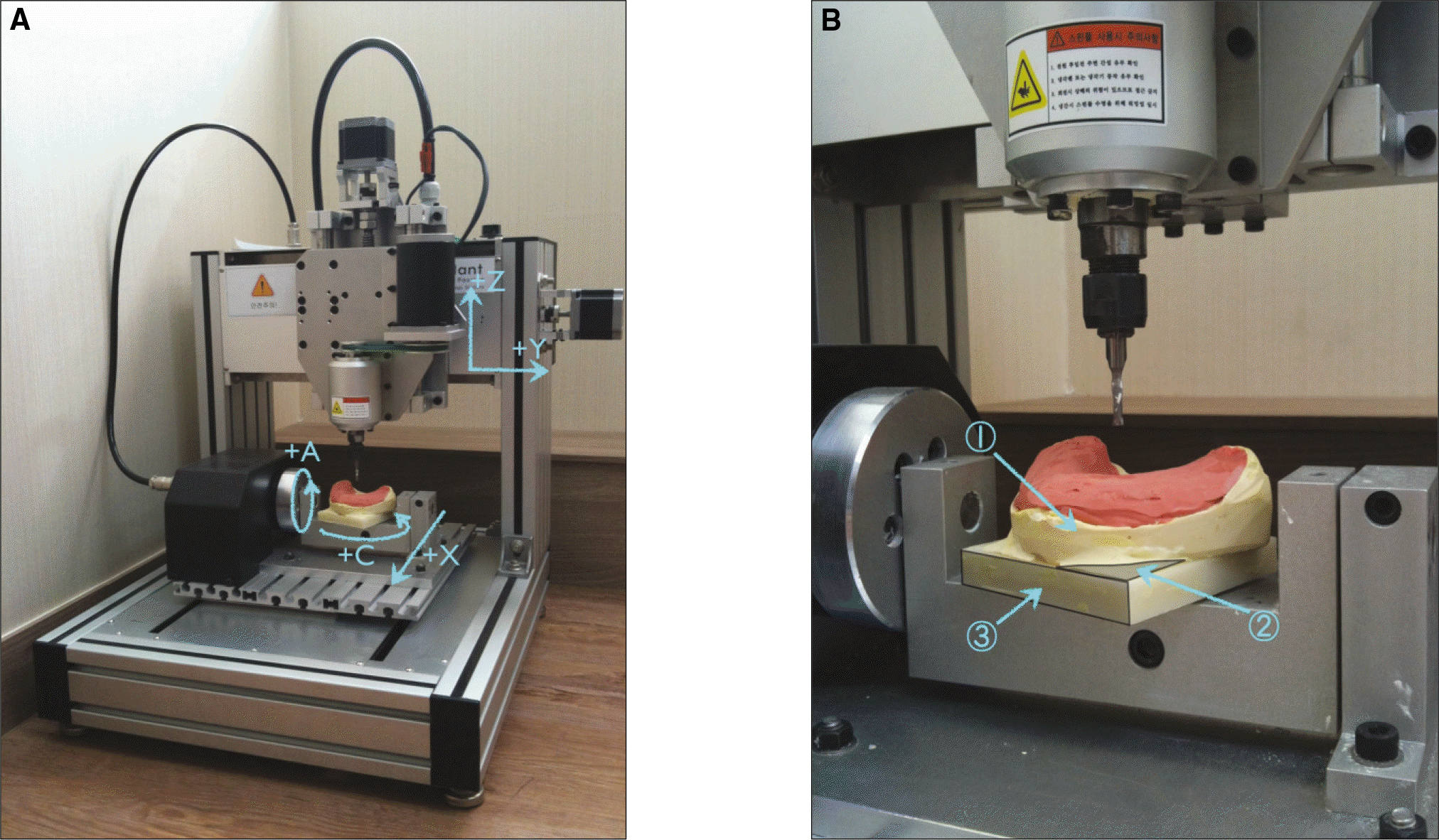 | Fig. 2.5-axis milling machine used in this study. A: Description of 5-axis path, B: Enlarged view of 5-axis milling machine. ① Experimental model, ② Platform for synchordination, ③ Synchordination plate. |
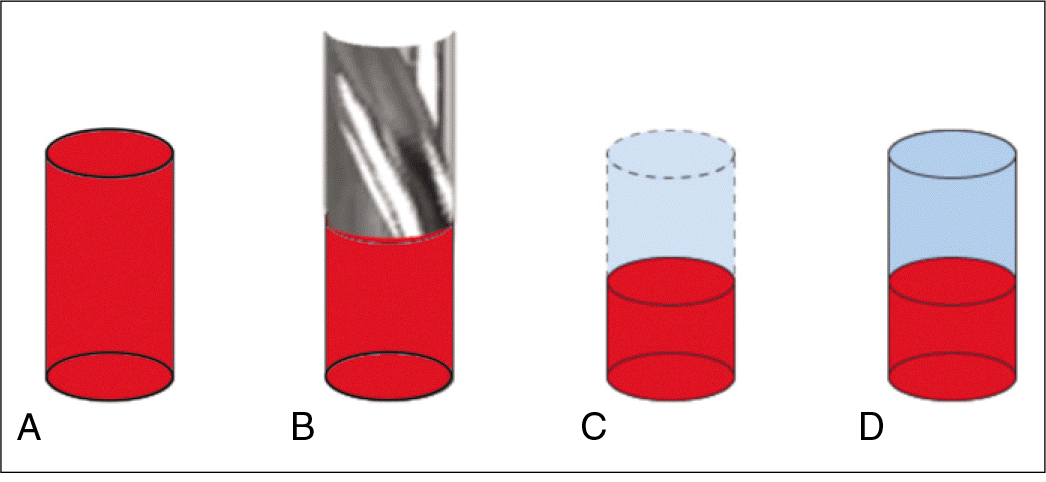 | Fig. 3.Overview of milling procedure. A: hidden dental stopping, B: milling with 3.28 mm drill, C: remaining stopping, D: merging and comparative analysis. |
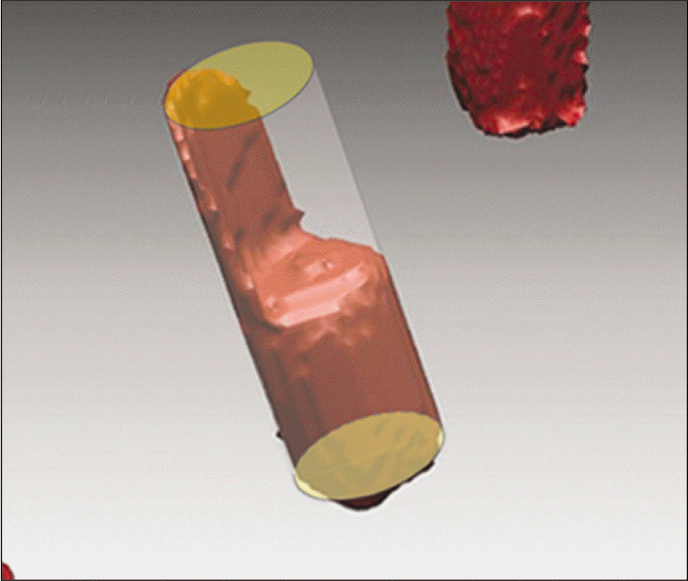
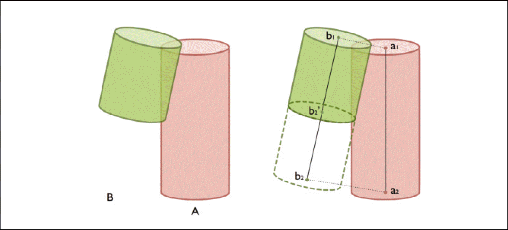 | Fig. 4.Reverse engineering procedure for determining center points of upper and lower part of the objects. A: Virtually planned object, B: Actual drilled bore. |
 XML Download