Abstract
Statement of problem
A casting connection technique is widely used for repair, correction and addition to base metal framework. However, a casting connection technique may increase the risk of failure in clinical situations when high stresses exist.
Purpose
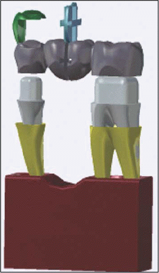
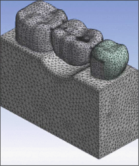
The purpose of this study was to investigate the mechanical retentive groove design comparatively to increase the joint strength by using the three-dimensional finite element analysis model of a 3-unit fixed partial denture.
Material and methods
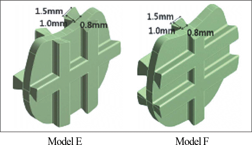
Ten finite element models were constructed. (Model A: One retentive groove, Model B: Two retentive grooves, Model C: Three retentive grooves, Model D: Four retentive grooves, Model E: One horizontal groove and two vertical grooves, Model F: Two horizontal grooves and one vertical groove, Model G: One groove with the enlarged dimension, Model H: Two grooves with the enlarged dimension, Model I: One groove with the increased height, Model J: One groove with the increased width of base). The vertical force was applied to the mesial and the distal fossa to the casting connection of mandibular first molar.
Results
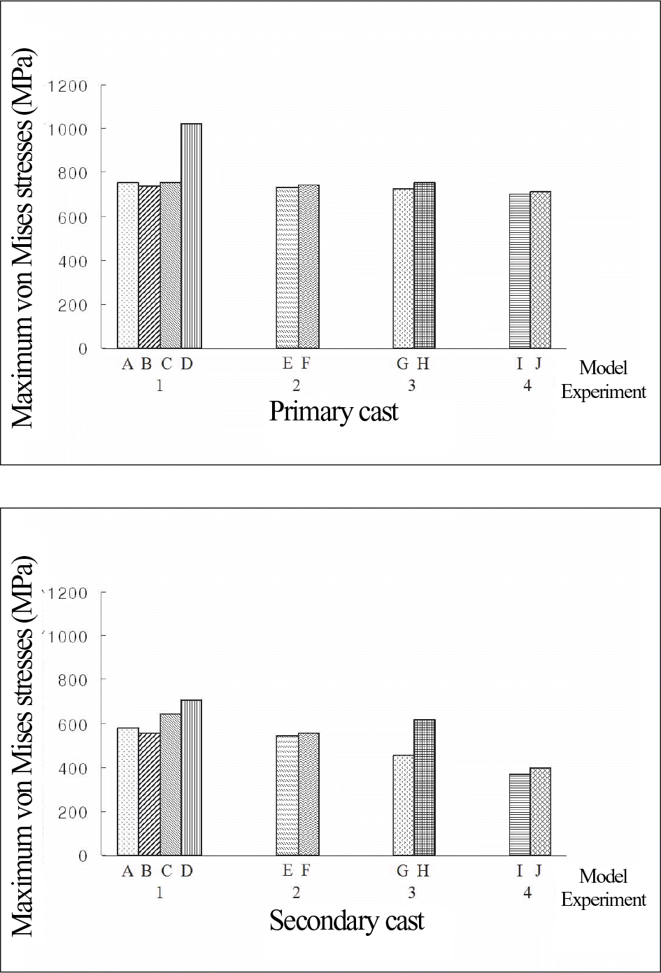
The main factors, affecting joint strength of casting connection were both the retention between the primary cast and the secondary cast and the thickness of the primary cast remaining after preparing retentive groove. The increase of retentive force, according to the numbers and the dimension of retentive groove had an effect on distributing stress. However, in some cases, the increase of retentive force resulted in the increase of stress by reducing thickness of the primary cast in the connection area.
Go to : 
REFERENCES
1.Weiss PA., Munyon RE. Repairs, corrections and additions to nonprecious ceramo-metal frameworks (II). Quintessence Dent Technol. 1980. 4:45–58.
2.DeHoff PH., Anusavice KJ., Evans J., Wilson HR. Effectiveness of cast-joined Ni-Cr-Be structures. Int J Prosthodont. 1990. 3:550–4.
3.Minagi S., Tanaka T., Sato T., Matsunaga T. Double-casting method for fixed prosthodontics with functionally generated path. J Prosthet Dent. 1998. 79:120–4.

4.Fehling AW. Cast connectors as cores for ceramometal pontics on removable partial dentures and for splinting anterior crowns. J Prosthet Dent. 1990. 63:167–71.

5.McCartney JW., Pearson R. Stabilization investment template for direct casting connection of implant framework segments. J Prosthet Dent. 1997. 78:106–8.

6.Fehling AW., Sansom BP., Meiser ET., Johnson PF. Cast connectors: an alternative to soldering base metal alloys. J Prosthet Dent. 1986. 55:195–7.

7.Seol YH., Jeong CM., Jeon YC., Kang SW. Fit of implant frameworks fabricated by one-piece casting, laser welding, soldering, and electric discharge machining. J Korean Acad Prosthodont. 2002. 40:156–71.
8.Zoidis PC., Winkler S., Karellos ND. The effect of soldering, electrowelding, and cast-to procedures on the accuracy of fit of cast implant bars. Implant Dent. 1996. 5:163–8.

9.Romero GG., Engelmeier R., Powers JM., Canterbury AA. Accuracy of three corrective techniques for implant bar fabrication. J Prosthet Dent. 2000. 84:602–7.

10.Jeong CM., Jeon YC., Lim JS. Flexure strength of cast-joined connector with Ni-Cr-Be alloy. J Korean Acad Prosthodont. 1998. 36:858–66.
11.Jeong CM. Effect of the undercut in retention grooves on flexure strength of cast-joined connector with Ni-Cr-Be alloy. J Pusan National University Hospital. 2000. 8:221–7.
12.Bertolotti RL., Napolitano LH. Strength of cast-joined nonprecious alloy frameworks. J Dent Res. 1984. 63(special is-sue):208 (abstr no. 334).
13.Son HO., Lee TJ., Jeong JH, et al. Dental anatomy. 5th ed.Seoul: Jeesung Publishing Inc.;2001. p. 151–7. p. 179–92.
14.Wheeler RC. Dental anatomy, Physiology and occlusion. 6th ed.Philadelphia;WB Saunders;1984. p. 184–287.
15.Carranza FA. Glickman' s clinical periodontology. 7th ed.Philadelphia;WB Saunders;1990. p. 47–8.
16.Goel VK., Khera SC., Gurusami S., Chen RC. Effect of cavity depth on stresses in a restored tooth. J Prosthet Dent. 1992. 67:174–83.

17.Farah JW., Craig RG., Meroueh KA. Finite element analysis of three- and four-unit bridges. J Oral Rehabil. 1989. 16:603–11.

18.Khera SC., Goel VK., Chen RC., Gurusami SA. A three-dimensional finite element model. Oper Dent. 1988. 13:128–37.
19.Morris HF. Veterans Administration Cooperative Studies Project No. 147/242. Part VII: The mechanical properties of metal ceramic alloys as cast and after simulated porcelain firing. J Prosthet Dent. 1989. 61:160–9.

20.Benzing UR., Gall H., Weber H. Biomechanical aspects of two different implant-prosthetic concepts for edentulous maxillae. Int J Oral Maxillofac Implants. 1995. 10:188–98.
21.Howell AH., Manly RS. An electronic strain gauge for measuring oral forces. J Dent Res. 1948. 27:705–12.

22.Rabinowicz E. Friction and wear of materials. 2nd ed.John Wiley & Sons Inc.;1995. p. 117.
23.Thoupos GA., Zouras CS., Winkler S., Roussos VG. Connecting implant framework segments. Implant Dent. 1995. 4:97–9.
25.Yang HS., Lang LA., Felton DA. Finite element stress analysis on the effect of splinting in fixed partial dentures. J Prosthet Dent. 1999. 81:721–8.

26.Jeong CM., Lee HY. A finite element stress analysis of the stress distribution and the shock absorption in an osseointe-grated implant-natural tooth supported fixed partial denture. J Korean Acad Prosthodont. 1992. 30:582–610.
Go to : 
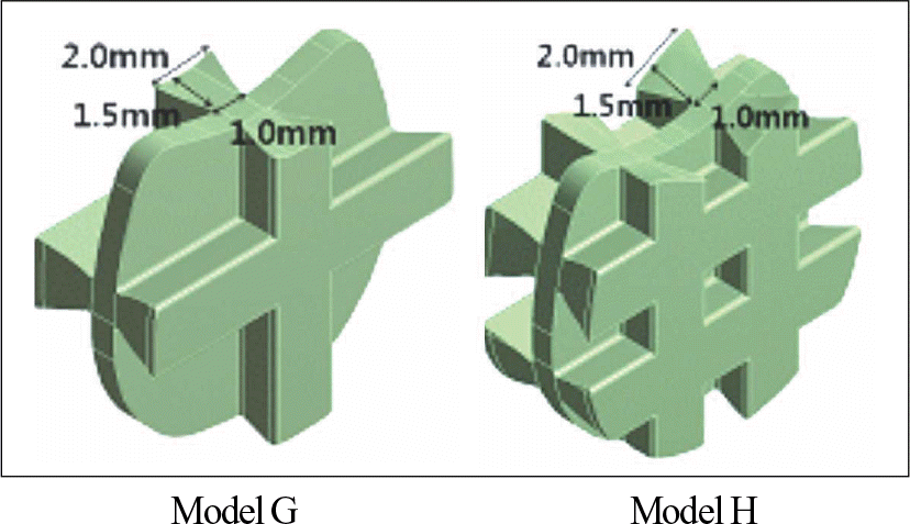 | Fig. 5.Experiment 3: Retentive grooves with the enlarged dimension in comparison with model A and B of experiment 1. |
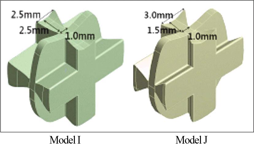 | Fig. 6.Experiment 4: Retentive grooves with the increased height (model I) or width of base (model J) in comparison with model G of experiment 3. |
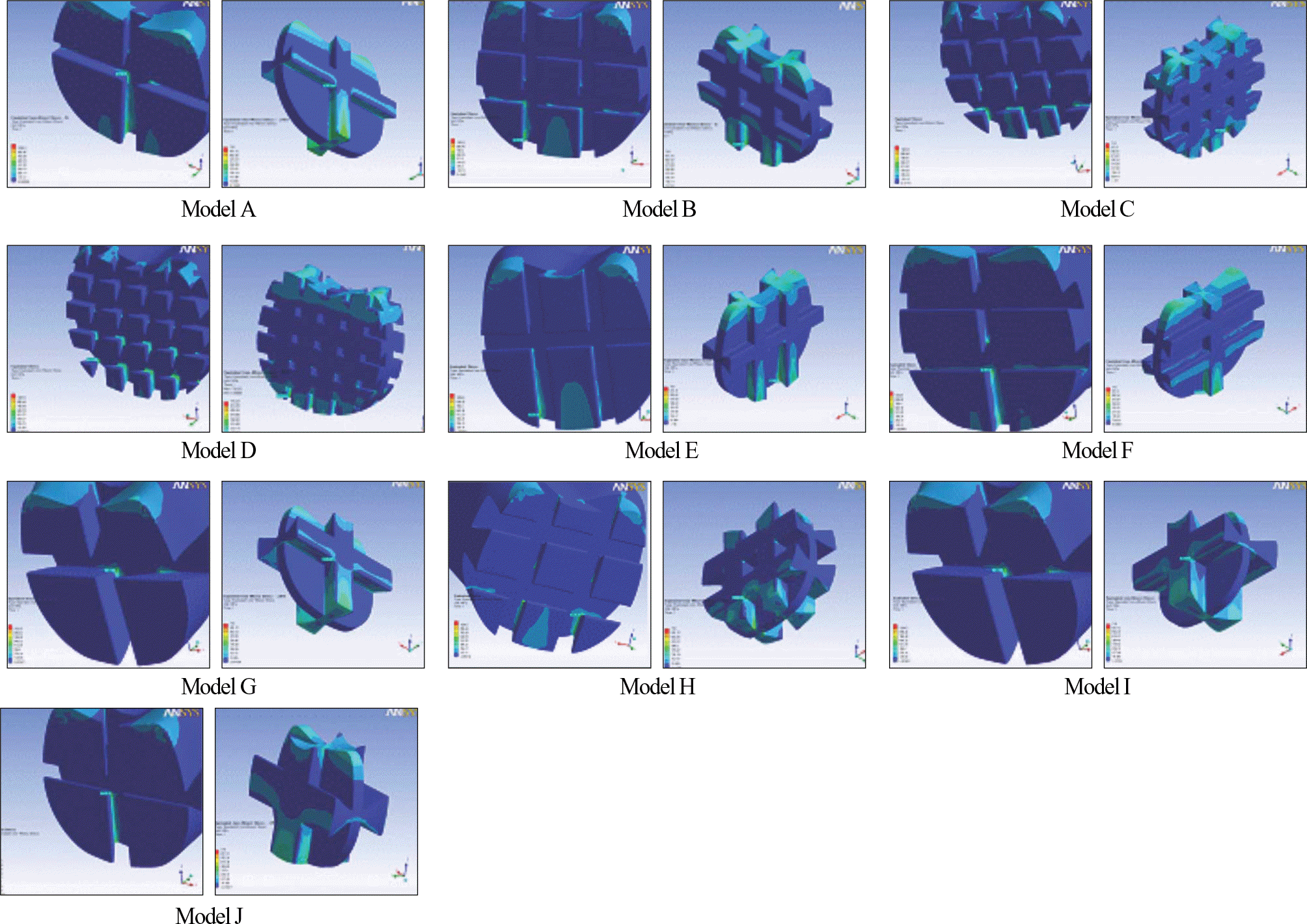 | Fig. 8.Distribution of von Mises stresses of the primary (left) and the secondary (right) cast of each model from experiment 1 to experiment 4. |
Table I.
Experimental condition of the casting connection


 PDF
PDF ePub
ePub Citation
 Print
Print



 XML Download