Abstract
Statement of problem
Loosening or fracture of the abutment screw is one of the common problems related to the dental implant. Generally, in order to make the screw joint stable, the preload generated by tightening torque needs to be increased within the elastic limit of the screw. However, additional tensile forces can produce the plastic deformation of abutment screw when functional loads are superimposed on preload stresses, and they can elicit loosening or fracture of the abutment screw. Therefore, it is necessary to find the optimum tightening torque that maximizes a fatigue life and simultaneously offer a reasonable degree of protection against loosening.
Purpose
The purpose of this study was to present the influence of tightening torque on the implant-abutment screw joint stability with the 3 dimensional finite element analysis.
Material and methods
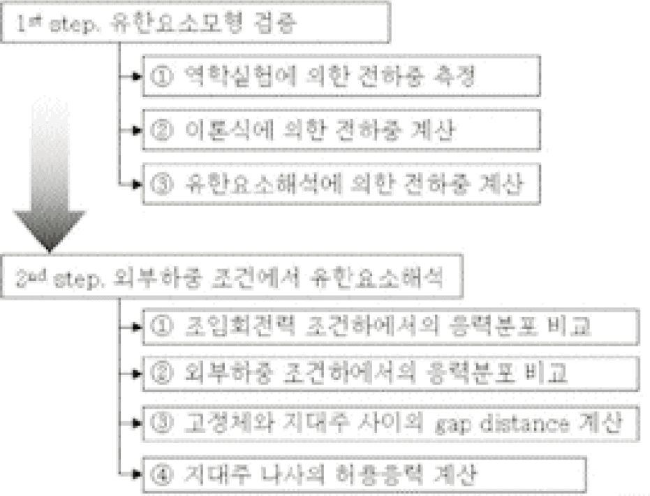
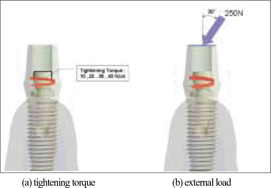
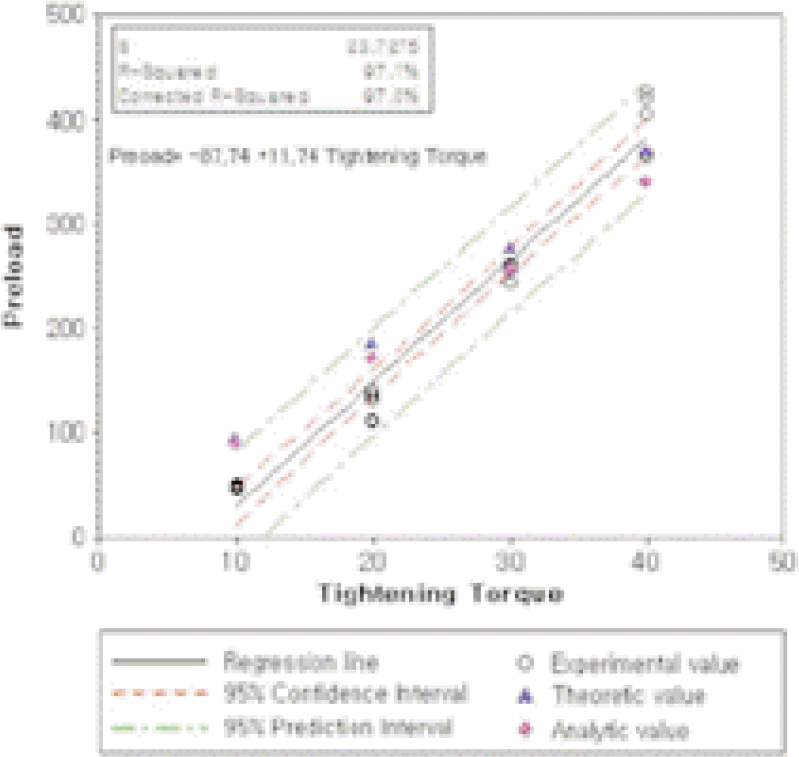
In this study, the finite element model of the implant system with external butt joint connection was designed and verified by comparison with additional theoretical and experimental results. Four different amount of tightening torques (10, 20, 30 and 40 Ncm) and the external loading (250 N, 30°) were applied to the model, and the equivalent stress distributions and the gap distances were calculated according to each tightening torque and the result was analyzed.
Results
Within the limitation of this study, the following results were drawn; 1) There was the proportional relation between the tightening torque and the preload. 2) In case of applying only the tightening torque, the maximum stress was found at the screw neck. 3) The maximum stress was also shown at the screw neck under the external loading condition. However in case of applying 10 Ncm tightening torque, it was found at the undersurface of the screw head. 4) The joint opening was observed under the external loading in case of applying 10 Ncm and 20 Ncm of tightening torque. 5) When the tightening torque was applied at 40 Ncm, under the external loading the maximum stress exceeded the allowable stress value of the titanium alloy.
REFERENCES
1.Adell R., Lekholm U., Rockler B., Bra � nemark PI. A 15-year study of osseointegrated implants in the treatment of edentulous jaw. Int J Oral Surg. 1981. 10:387–416.
2.Albrektsson T. A multicenter report on osseointegrated oral implants. J Prosthet Dent. 1988. 60:75–84.

3.Johansson G., Palmqvist S. Complications supplementary treatment and maintenance in edentulous arches with implant-supported fixed prostheses. Int J Prosthodont. 1990. 3:89–92.
4.Tolman DE., Laney WR. Tissue-integrated prosthesis complications. Int J Oral Maxillofac Implants. 1992. 7:477–84.

5.Carlson B., Carlsson GE. Prosthodontic complications in osseointegrated dental implant treatment. Int J Oral Maxillofac Implants. 1994. 9:90–4.

6.Hemmings KW., Schmitt A., Zarb GA. Complications and maintenance requirements for fixed prostheses and over-dentures in the edentulous mandible: a 5-year report. Int J Oral Maxillofac Implants. 1994. 9:191–6.
7.Jemt T., Pattersson P. A 3-year follow-up study on single implant treatment. J Dent. 1993. 21:203–8.

8.Jorneus L., Jemt T., Carlsson L. Loads and designs of screw joints for single crowns supported by osseointegrated implants. Int J Oral Maxillofac Implants. 1992. 7:353–9.
9.Misch CE. Principles for screw-retained prostheses. Misch CE, editor. Contemporary implant dentistry,. Missouri: CV Mosby;1999.
10.Bickford JH. An Introduction to the design and behavior of bolted joints. New York: Marcel Dekker;1995.
11.Sakaguchi RL., Sun T., Haack JE. External strain distribution on implant prosthetic components. J Dent Res. 1994. 71(special issue):232.
12.McGlumphy EA., Mendel DA., Holloway JA. Implant screw mechanics. Dent Clin North Am. 1998. 42:71–89.
13.Burguete RL., Johns RB., King T., Patterson EA. Tightening characteristics for screwed joints in osseointegrated dental implants. J Prosthet Dent. 1994. 71:592–9.

14.Jorneus L., Jemt T., Carlsson L. Loads and designs of screw joints for single crowns supported by osseointegrated implants. Int J Oral Maxillofac Implants. 1992. 7:353–9.
15.Jaarda MJ., Razzoog ME., Gratton DG. Comparison of “Look-Alike”implant prosthetic retaining screws. J Prosthodont. 1995. 4:23–7.
16.Binon P., Franz ., Brunski J., Gulbransen H. The role of screws in implant systems. Int J Oral Maxillofac Implants. 1994. 9:48–63.
17.Rangert B., Jemt T., Jo ¨rneus L. Forces and moments on Bra � nemark implants. Int J Oral Maxillofac Implants. 1989. 4:241–7.
18.Weiss EI., Kozak D., Gross MD. Effect of repeated closures on opening torque values in seven abutment-implant systems. J Prosthet Dent. 2000. 84:194–9.

19.Haack JE., Sakaguchi RL., Sun T., Coffey JP. Elongation and preload stress in dental implant abutment screws. Int J Oral Maxillofac Implants. 1995. 10:529–36.
20.Griffith HT. Suggested tightening torques for structural bolts. Fastener Technology/February. 1987.
21.Shin HM., Jeong CM. Influence of tightening torque on implant - abutment screw joint stability. J Korean Acad Prosthodont. 2008. 46:396–408.
22.Lin CL., Wang JC. Nonlinear finite element analysis of a splinted implant with various connectors and occlusal Forces. Int J Oral Maxillofac Implants. 2003. 18:331–40.
23.Kang TH. Kim SG. Finite element stress analysis according to apical-coronal implant position. J Korean Oral Maxillofac Surg. 2006. 32:52–9.
24.Merz BR., Hunenbart S., Belser UC. Mechanics of the implant-abutment connection: an 8-degree taper compared to a butt joint connection. Int J Oral Maxillofac Implants. 2000. 15:519–26.
25.Sakaguchi RL., Borgersen SE. Nonlinear contact analysis of preload in dental implant screws. Int J Oral Maxillofac Implants. 1995. 10:295–302.
26.Genna F. Shakedown self-stresses, and unilateral contact in a dental implant problem. J Euromchsol. 2004. 23:485–98.

27.Ekici B. Numerical analysis of a dental implant system in three-dimension. Advances in Engineering Software. 2002. 33:109–13.

28.Alkan I., Sertgo ¨z A., Ekici B. Inflence of occlusal forces on stress distribution in preload dental implant screws. J Prosthet Dent. 2004. 91:319–25.
29.Boyer R., Welsch G., Collings EW. Materials properties handbook: Titanium alloys. ASM International: Materials Park;1994.
30.John M., Tim H. Structural alloys handbook. West Lafayette: CINDAS;1996.
31.O' Brien WJ. Dental materials and their selection. 2nd ed.Chicago: Quintessence;1997.
32.Cibirka RM., Razzoog ME., Lang BR., Stohler CS. Determining the force absorption quotient for restorative Materials used in implant occlusal surfaces. J Prosthet Dent. 1992. 361–4.

33.Jeong CM., Lee HY. A finite element stress analysis of the stress distribution and the shock absorption in an osseointegrated implant-natural tooth supported fixed partial denture. J Korean Acad Prosthodont. 1992. 30:493–521.
34.Davis JR. Concise Metals Handbook. ASM International;1997.
35.Gibb CH., Mahan PE., Mauderli A., Lundeen HC. Walsh EK. Limits of human bite strength. J Prosthet Dent. 1986. 56:226–9.
36.ISO/DIS 14801. Dentistry-Fatigue test for endosseous dental implants. International Organization for Standardization;2005.
37.Lee YB., Chang HS. Synthetic machine design. CMG book;2001. p. 112–6.
38.Lazzara RJ. Criteria for implant selection: surgical and prosthetic considerations. Pract Periodontics Aesthet Dent. 1994. 6:55–62.
39.Patterson EA., Johns RB. Theoretical analysis of the fatigue life of fixture screws in osseointegrated dental implants. Int J Oral Maxillofac Implants. 1992. 7:26–34.
40.Lang LA., Kang B., Wang R., Lang BR. Finite element analysis to determine implant preload. J Prosthet Dent. 2003. 90:539–46.

41.David DG., Aquilino SA., Stanford CM. Micromotion and dynamic fatigue properties of the dental implant-abutment interface. J Prosthet Dent. 2001. 85:47–52.
Table I.
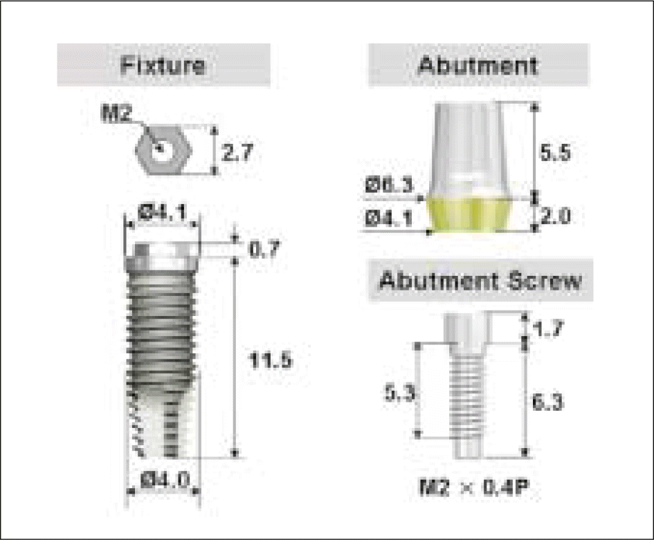
Specification of experimental materials
| Components | Sizes | Material |
|---|---|---|
| US II Fixture | ∅ 4.1 mm × L 11mm | Titanium Gr. 4 |
| Cement Abutment | ∅ 5.0 mm × H 5.5 mm | Titanium Gr. 3 |
| Abutment Screw | M 2.0 × 0.4 P | Ti-6Al-4V |
Table II.
Material properties 29-33
| Material | Young's modulus | Poisson's ratio | |
|---|---|---|---|
| Fixture | Ti Gr4 | 105 GPa | 0.34 |
| Abutment | Ti Gr3 | 104 GPa | 0.34 |
| Screw | Ti-6Al-4V | 113 GPa | 0.342 |
| Cortical Bone | - | 13.7 GPa | 0.3 |
| Cancellous Bone | e - | 1.37 GPa | 0.3 |
Table III.
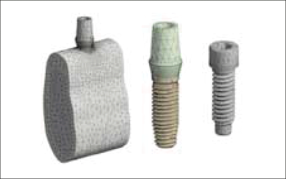
Number of nodes and elements at FE-model
Table IV.
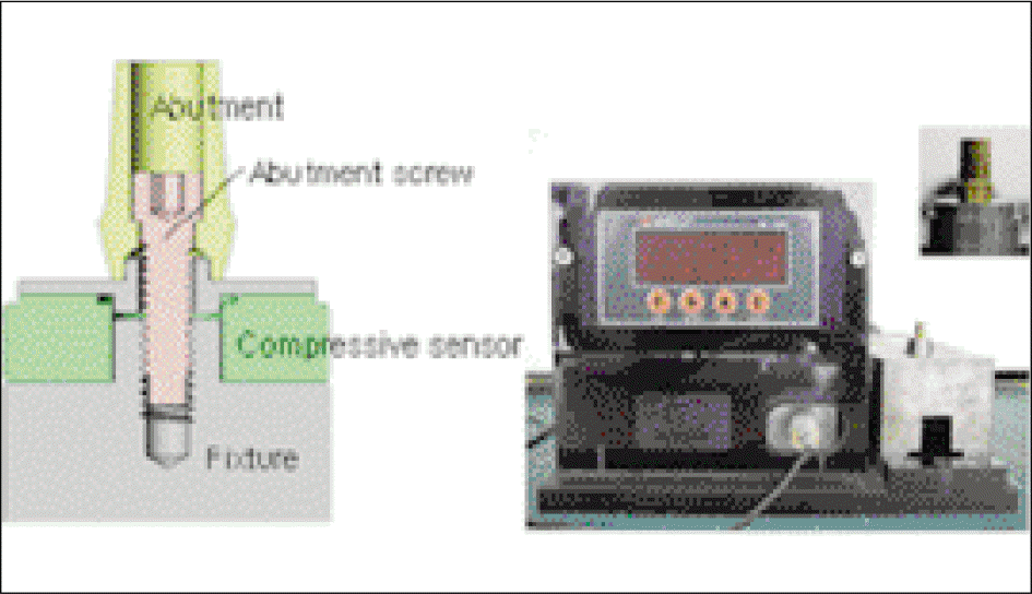
Mean values ± SDs of measured preload [N]
| Tightening torque | n | Mean ± SD∗ [N] |
|---|---|---|
| 10 Ncm | 5 | 47.7 ± 2.1 a |
| 20 Ncm | 5 | 126.0 ± 14.2b |
| 30 Ncm | 5 | 253.0 ± 9.2 c |
| 40 Ncm | 5 | 396.7 ± 29.1d |
Table V.
Preload [N] calculated by theoretical formula
| Tightening torque | ||||
|---|---|---|---|---|
| 10 Ncm | 20 Ncm | 30 Ncm | 40 Ncm | |
| Preload [N] | 90.6 | 181.2 | 271.8 | 362.4 |
Table VI.
Measured Preload [N] from FEA
| Tightening torque | ||||
|---|---|---|---|---|
| 10 Ncm | 20 Ncm | 30 Ncm | 40 Ncm | |
| Preload [N] at Abutment and Screw interface | 81.3 | 161.6 | 238.2 | 342 |
| Preload [N] at Abutment and Fixture interface | 81.3 | 161.6 | 238.2 | 342 |


 PDF
PDF ePub
ePub Citation
 Print
Print




 XML Download